Rockwell Automation 20-COMM-D DeviceNet Adapter Series B FRN 2.xxx User Manual
Page 107
Using the I/O
5-23
20-COMM-D DeviceNet Adapter User Manual
Publication 20COMM-UM002G-EN-P
Understanding PLC-5 Controller Data Table Addresses
Because the PLC-5 controller is a 16-bit platform and is used with the
32-bit 20-COMM-D adapter, the data will be transposed from the
least-significant word (LSW) to the most-significant word (MSW) in the
controller.
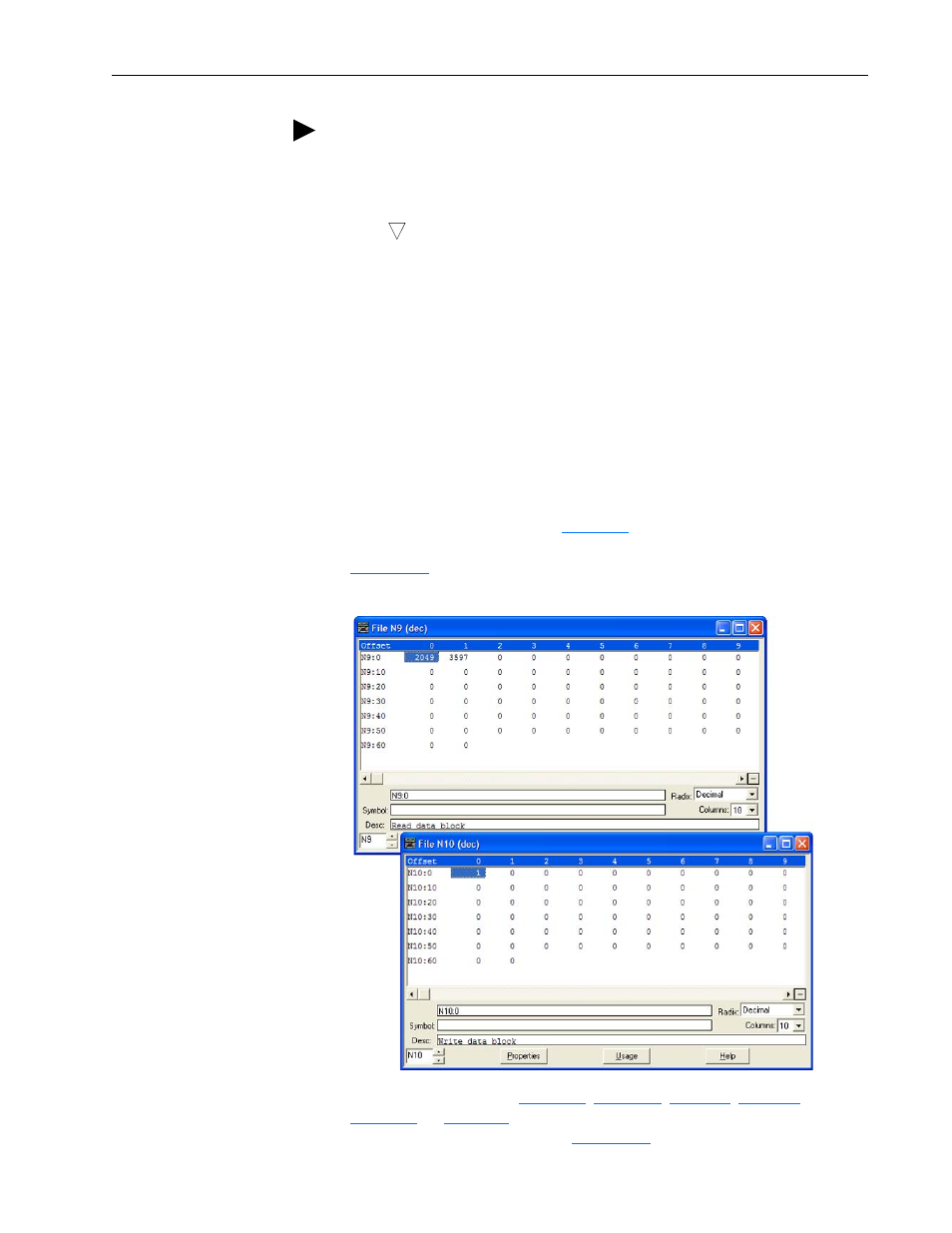
When the I/O was configured (
), two available data table
addresses (N9:0 for input data and N10:0 for output data) were used.
shows the entire data file address structure for this example.
Figure 5.15 Data File Table for Example Ladder Logic Program
Depending on the drive,
, or
show the I/O definitions as they relate to the N9:0
and N10:0 data table addresses (
) being used in this example.
TIP: When using a drive that has 16-bit Datalinks (PowerFlex 70,
PowerFlex 700, and PowerFlex 700H drives) to transfer a 32-bit parameter,
two contiguous drive Datalink parameters (for example, Data Out A1/A2,
B1/B2, and so forth) are required. To determine if a parameter is a 32-bit
parameter, see the Parameter section in the drive documentation and look
for a
symbol in the ‘No.’ column. (All parameters in PowerFlex 700
Series B drives are 32-bit parameters.) For example, parameter 3 - [Output
Current] in a PowerFlex 70 EC drive is a 32-bit parameter. When using a
drive that has 32-bit Datalinks (PowerFlex 700 VC, PowerFlex 700S, and
PowerFlex 750-Series drives), only one drive Datalink parameter is required
to transfer any parameter.
32