Drive and adapter parameter settings – Rockwell Automation 20-COMM-D DeviceNet Adapter Series B FRN 2.xxx User Manual
Page 118
5-34
Using the I/O
20-COMM-D DeviceNet Adapter User Manual
Publication 20COMM-UM002G-EN-P
Drive and Adapter Parameter Settings
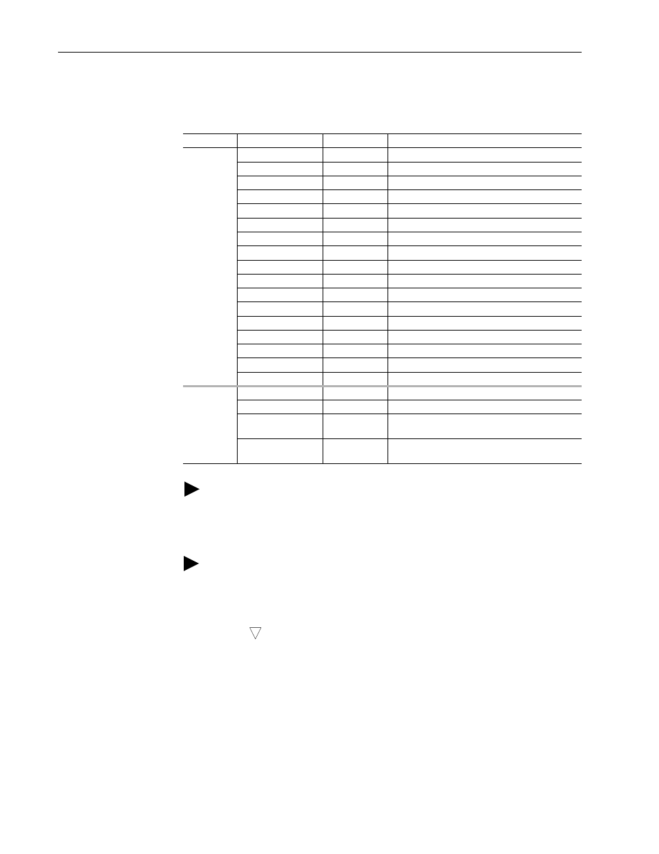
The following drive and adapter settings were used for the example ladder
logic program in this section.
Device
Parameter
Value
Description
PowerFlex
70 EC Drive
90 - [Speed Ref A Sel 22 (DPI Port 5)
Assigns 20-COMM-D to be used for the Reference.
300 - [Data In A1]
140
Points to Par. 140 - [Accel Time 1]
301 - [Data In A2]
142
Points to Par. 142 - [Decel Time 1]
302 - [Data In B1]
100
Points to Par. 100 - [Jog Speed]
303 - [Data In B2]
155
Points to Par. 155 - [Stop Mode A]
304 - [Data In C1]
101
Points to Par. 101 - [Preset Speed 1]
305 - [Data In C2]
102
Points to Par. 102 - [Preset Speed 2]
306 - [Data In D1]
103
Points to Par. 103 - [Preset Speed 3]
307 - [Data In D2]
104
Points to Par. 104 - [Preset Speed 4]
310 - [Data Out A1]
140
Points to Par. 140 - [Accel Time 1]
311 - [Data Out A2]
142
Points to Par. 142 - [Decel Time 1]
312 - [Data Out B1]
100
Points to Par. 100 - [Jog Speed]
313 - [Data Out B2]
155
Points to Par. 155 - [Stop Mode A]
314 - [Data Out C1]
101
Points to Par. 101 - [Preset Speed 1]
315 - [Data Out C2]
102
Points to Par. 102 - [Preset Speed 2]
316 - [Data Out D1]
103
Points to Par. 103 - [Preset Speed 3]
317 - [Data Out D2]
104
Points to Par. 104 - [Preset Speed 4]
20-COMM-D
Adapter
03 - [DN Addr Cfg]
2
Node address for the adapter.
13 - [DPI I/O Cfg]
xxx1 1111
Enables Cmd/Ref and Datalinks A…D.
25 - [M-S Input]
xxx1 1111
Configures the I/O Data to be transferred from the
controller on the network to the drive.
26 - [M-S Output]
xxx1 1111
Configures the I/O Data to be transferred from the
drive to the controller on the network.
TIP: Data In parameters are inputs into the drive that come from controller
outputs (for example, data to write to a drive parameter). Data Out
parameters are outputs from the drive that go to controller inputs (for
example, data to read a drive parameter).
TIP: When using a drive that has 16-bit Datalinks (PowerFlex 70,
PowerFlex 700, and PowerFlex 700H drives) to transfer a 32-bit parameter,
two contiguous drive Datalink parameters (for example, Data Out A1/A2,
B1/B2, and so forth) are required. To determine if a parameter is a 32-bit
parameter, see the Parameter section in the drive documentation and look
for a
symbol in the ‘No.’ column. (All parameters in PowerFlex 700
Series B drives are 32-bit parameters.) For example, parameter 3 - [Output
Current] in a PowerFlex 70 EC drive is a 32-bit parameter. When using a
drive that has 32-bit Datalinks (PowerFlex 700 VC, PowerFlex 700S, and
PowerFlex 750-Series drives), only one drive Datalink parameter is required
to transfer any parameter.
32