Plc-5 controller example, Plc-5 controller example -19 – Rockwell Automation 20-COMM-D DeviceNet Adapter Series B FRN 2.xxx User Manual
Page 103
Using the I/O
5-19
20-COMM-D DeviceNet Adapter User Manual
Publication 20COMM-UM002G-EN-P
PLC-5 Controller Example
Creating an RSLogix 5 Project, Version 7.20 or Later
To transmit (read and write) data between the controller and drive, you must
create discrete I/O instructions in the controller for Logic Command/Status,
Reference/Feedback, and Datalinks.
1. Start RSLogix 5 software.
The RSLogix 5 window appears.
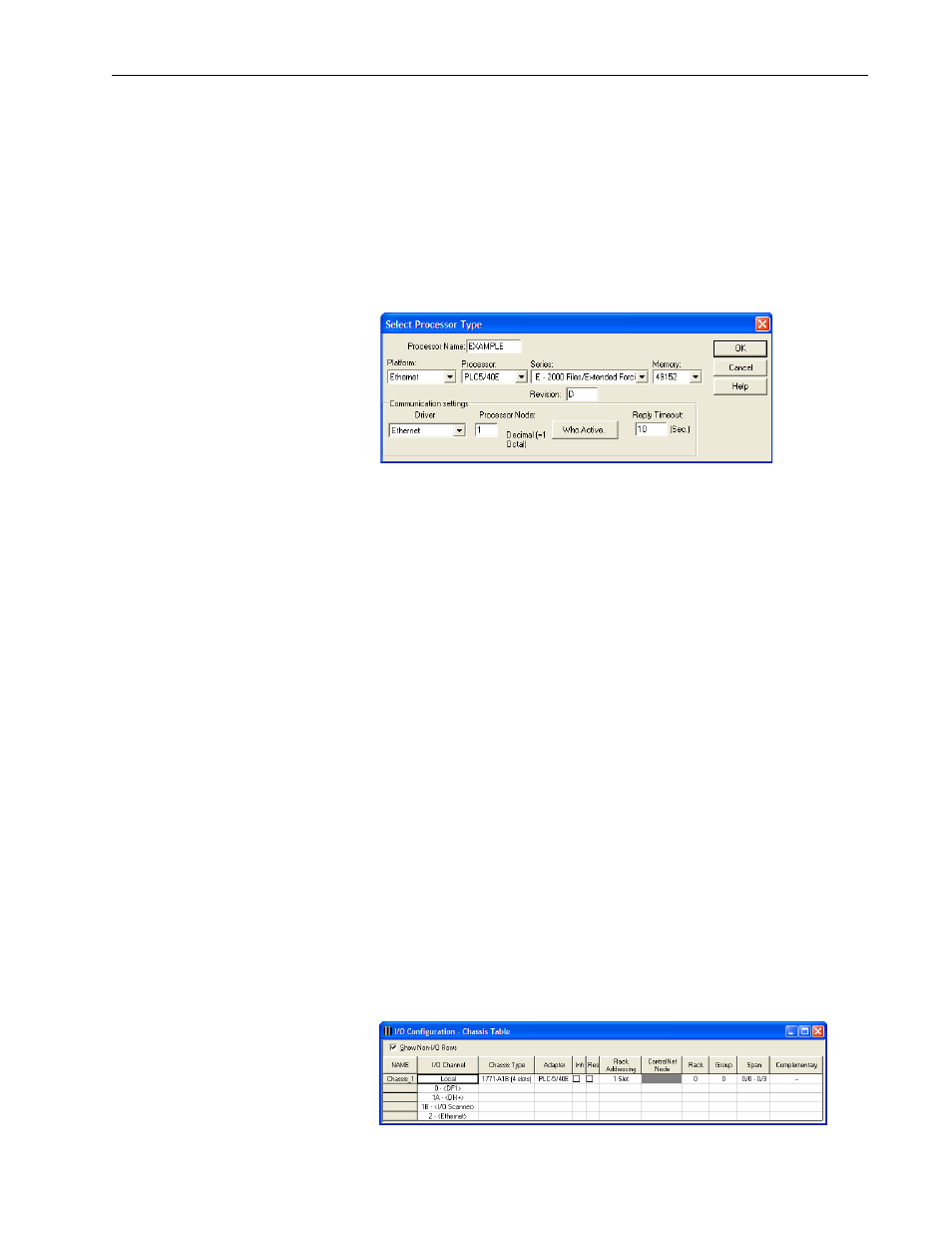
2. Select File > New to display the Select Processor Type screen.
3. Assign a name for the processor.
4. From the pull-down menus, choose the appropriate choices to match
your PLC-5 controller and application.
Important: Note that for this example, the processor being used has
direct Ethernet communication capability. DeviceNet
always uses a dedicated module (for example, 1771-SDN
scanner, and so forth) which cannot be used for a direct
PLC-5 processor connection. Therefore, this example
screen shows an Ethernet configuration.
5. Click OK.
The RSLogix 5 project window appears.
Creating Logic for Communication Between the 1771-SDN Scanner and
PLC-5 Processor
To transmit (read and write) data between the 1771-SDN DeviceNet scanner
and PLC-5 processor, you must create message instructions that allocate
data table addresses in the controller. By doing the following configuration,
RSLogix 5 software automatically creates the needed logic rungs for this
communication.
1. In the RSLogix 5 project treeview left pane, double-click IO
Configuration to display the I/O Configuration - Chassis Table screen.