Validating i/o layout, Validating i/o layout -3 – Rockwell Automation 5730 DriveLogix5730 Controller for PowerFlex 700S Drives with Phase II Control User Manual
Page 53
Placing and Configuring Local I/O
3-3
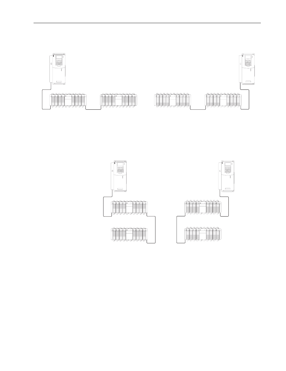
A 1769-CRL1/-CRL3 connects the left side of one bank of Compact I/O to
the right side of another. This facilitates a horizontal I/O orientation.
A 1769-CLL1/-CLL3 connects the left side of one bank of Compact I/O to
the left side of another. A 1769-CRR1/-CRR3 connects the right side of one
bank of Compact I/O to the right side of another. This facilitates a vertical
I/O orientation.
Validating I/O Layout
To validate your planned I/O layout, consider these requirements:
• Each module in a Compact I/O system uses a set amount of backplane
memory, in addition to the data that the module stores or transfers. As
you add modules, the minimum backplane RPI increases.
• The I/O modules must be distributed such that the current consumed
from the left or right side of the power supply never exceeds 2.0A at 5V
dc and 1.0A at 24V dc.
20D-DL2-CL3
1769-CRLX
20D-DL2-CR3
1769-CRLX
ahw0806.eps
ahw0808.eps
20D-DL2-CL3
1769-CRRX
20D-DL2-CR3
1769-CLLX
ahw080
9.eps
ahw0807.eps