Rockwell Automation 5730 DriveLogix5730 Controller for PowerFlex 700S Drives with Phase II Control User Manual
Page 153
Communicating with Devices on a ControlNet Link
7-13
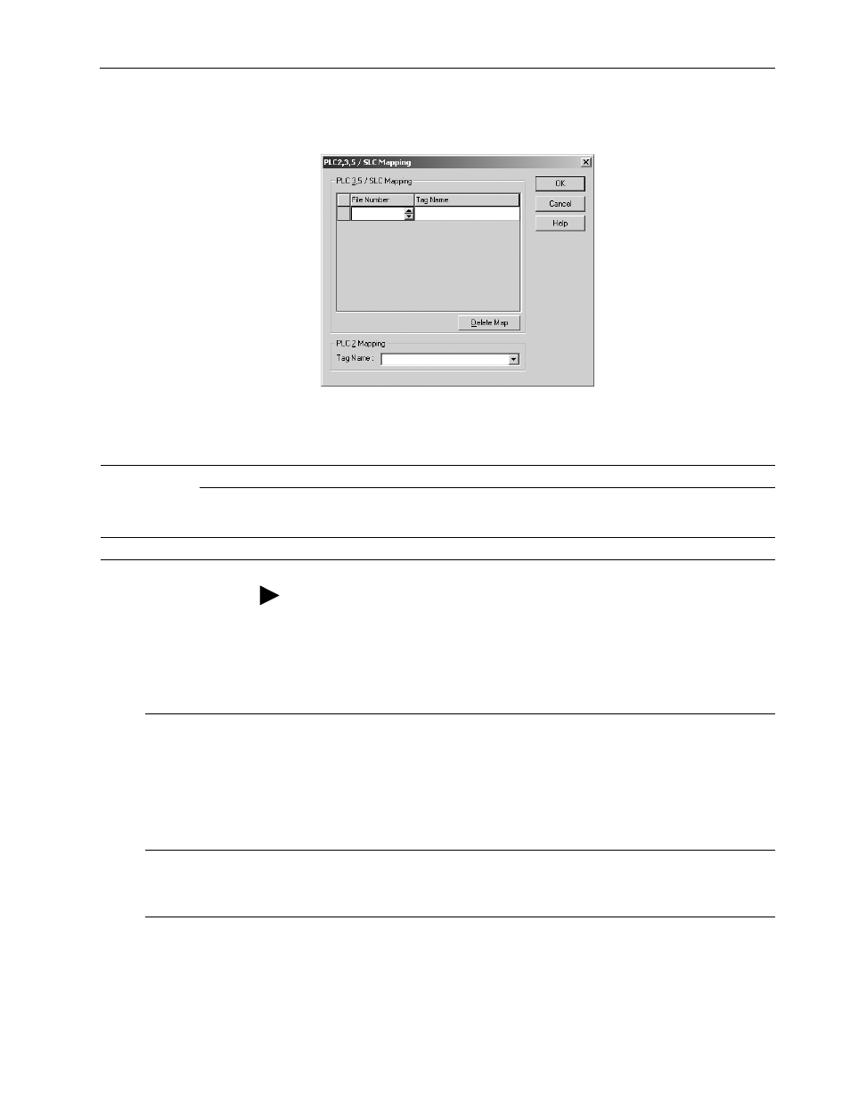
To map addresses:
1. From the Logic menu, select Map PLC/SLC Messages.
2. Specify this information:
The following table shows example source and destination tags and
elements for different controller combinations.
ahw08
89.tif
For:
In this field:
Specify:
For example:
PLC-3, PLC-5, and
SLC controllers
File Number
Type the file number of the data table in the PLC/SLC controller. 10
Tag Name
Type the array tag name the local controller uses to refer to the
PLC/SLC data table address. The tag must be an integer array
(SINT, INT, or DINT) that is large enough for the message data.
array_1
PLC-2 controllers
Tag Name
Type the tag name to be the PLC-2 compatibility file.
200
TIP: You can map as many tags as you want to a PLC-3, PLC-5, or SLC
controller. You can map only one tag to a PLC-2 controller.
Type of MSG Instruction:
Example Source and Destination:
PLC-5 writes to DriveLogix5730
SLC writes to DriveLogix5730
SLC 5/05
SLC 5/04 OS402 and above
SLC 5/03 OS303 and above
source element
N7:10
destination tag
“array_1”
The PLC-5, PLC-3, and SLC controllers support logical ASCII addressing so you do not have to
map a compatibility file for MSG instructions initiated by a PLC-5, PLC-3, or SLC controller. Place
the DriveLogix5730 tag name in double quotes (“).
You could optionally map a compatibility file. For example, if you enter 10 for the compatibility file,
you enter N10:0 for the destination tag.
PLC-2 writes to DriveLogix5730
source element
010
destination tag
200
The destination tag is the three-digit PLC-2 address you specified for PLC-2 mapping.