Rockwell Automation 20L PowerFlex 700L Frame 1X Liquid-Cooled Adjustable Frequency AC Drive User Manual
Page 42
PowerFlex 700L Frame 1X Drive Installation Instructions – Publication 20L-IN013A-EN-P – June 2009
42
– Speed/Torque Control & Direction Limits
– Speed Reference
– Start & Stop Modes
– Ramp Setup
– Digital and Analog I/O
– Application Set-up (TorqProve, Oil Well Pumps, Positioning/Speed
Profiling)
See
Running an Assisted Start Up on page 43
for details.
Important Information
Power must be applied to the drive when viewing or changing parameters.
Previous programming may affect the drive status and operation when
power is applied. If the I/O Cassette has been changed, a Reset Defaults
operation must be performed.
Torque Proving applications can use the Assisted Start Up to tune the motor.
However, it is recommended that the motor be disconnected from the hoist/
crane equipment during the routine. If this is not possible, refer to the
TorqProve Manual Start Up procedure in the PowerFlex 700 Series B User
Manual (publication 20B-UM002).
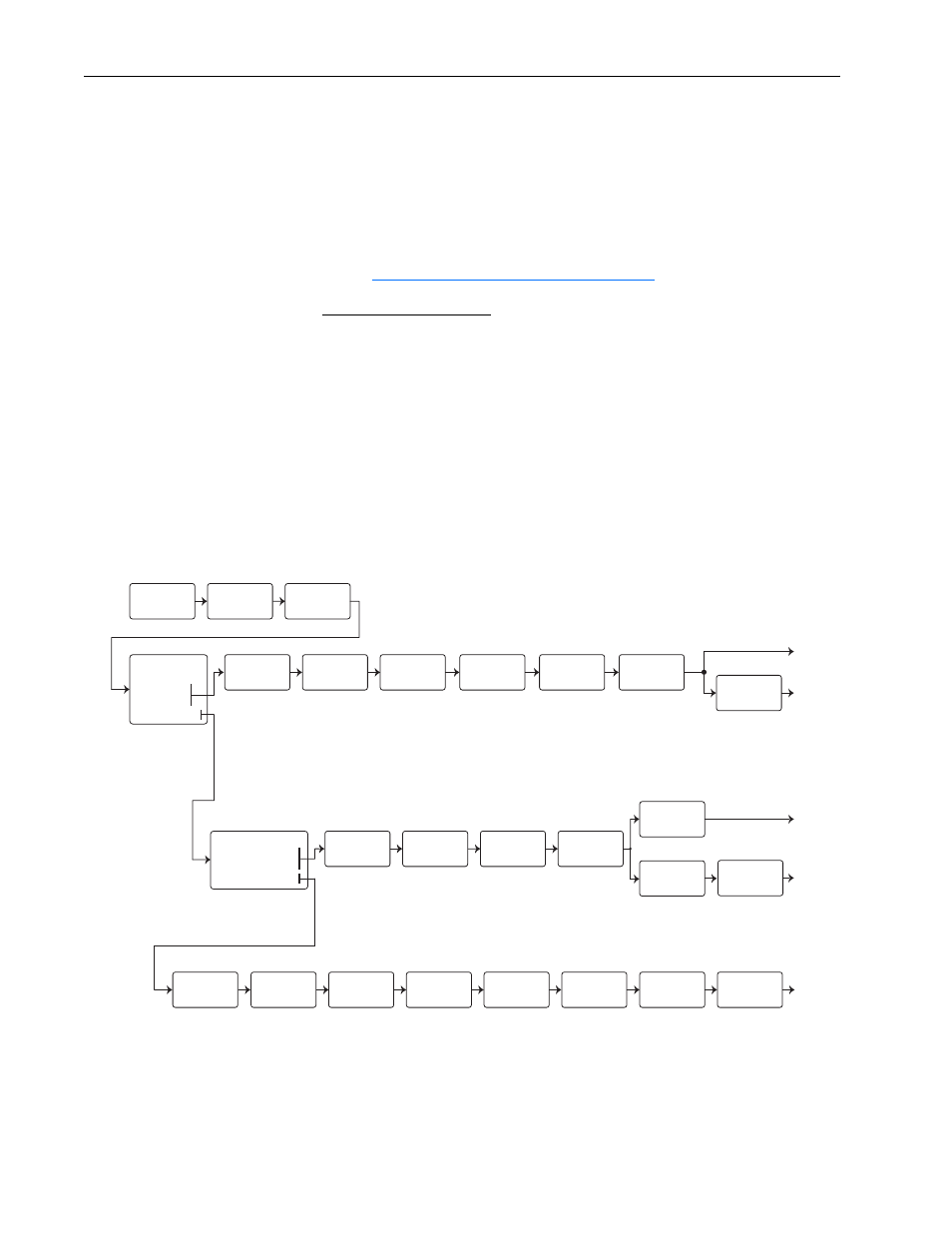
Figure 18
Start Up Menu
Configures
Motor Control
Method
Motor Control
Select
Enter Motor NP
Data, Stop Mode,
Accel/Decel
Ramp Times
Motor Data &
Ramp Times
Optimize Torque
and
Verify Direction
Motor
Tests
(1)
Set Min/Max
Speed and
Direction Control
Speed
Limits
Configure
Source, Value
and Scale for
Speed References
Speed/Torque
Control
Start/Stop/
I/O
Configure
Control Method
(2 Wire/3 Wire),
I/O, Digital I/O
& Analog Outputs
Configure for a
Specific Application
such as; Auto Restart,
Flying Start, etc.
Basic
Start-Up
Continue
Start Over
Intro
Configures
Motor Control
Method
Motor Control
Select
Enter Motor NP
Data, Stop Mode,
Accel/Decel
Ramp Times
Motor Data &
Ramp Times
Optimize Torque
and
Verify Direction
Motor
Tests
Set Min/Max
Speed and
Direction Control
Speed
Limits
Configure
Source, Value
and Scale for
Speed References
Speed/Torque
Control
Done /
Exit
Pos/Spd
Profile
Pos/Spd Profile
Done /
Exit
Torque
Proving
Torque Proving
Detailed
Application
Selection:
1. SMART
2. Basic
3. Detailed
4. Application
Enter Motor NP
Data, Stop Mode,
Accel/Decel
Ramp Times
Enter Pump
Data
(1)
During Motor Tests and tuning procedures, the drive may modify certain parameter values for proper Start Up operation. These values are then reset to their original values when
Start Up is complete. The affected Parameters are 053, 080, 276, 278, and 361…366. If power is removed from the drive during the tests without aborting the auto-tune procedure,
these parameters may not be reset to their original value. If this situation occurs, reset the drive to factory defaults and repeat the Start Up procedure.
Motor Data &
Ramp Times
Well Pump
Type
Optimize Torque
and
Verify Direction
Motor
Tests
Pump
Data
Start/Stop/
I/O
Configure
Control Method
(2 Wire/3 Wire),
I/O, Digital I/O
& Analog Outputs
Configure
Source, Value
and Scale for
Speed References
Speed/Torque
Control
Torque
Alarm
Process
Display
Done /
Exit
Selection:
1. Torq Prove
2. Pos/Spd Profile
3. Oil Well Pumps
Done /
Exit
Done /
Exit