Rockwell Automation 20L PowerFlex 700L Frame 1X Liquid-Cooled Adjustable Frequency AC Drive User Manual
Page 35
PowerFlex 700L Frame 1X Drive Installation Instructions – Publication 20L-IN013A-EN-P – June 2009
35
2. Determine the maximum voltage across R
MAX
using the following
equation:
V
MAX
= 1.00V x R
MAX
/ (R
MAX
+ 998)
3. Select the largest gain that results in V
MAX
* Gain (x10, x20, or x40),
being less than 10 volts.
Example:
Using a 100 Ohm Pt RTD (a = 0.00385) to measure temperatures from
0…200 °C, the maximum resistance occurs at 200 °C and is approximately
177 Ohm. The maximum voltage across the sensor is 151 mV. If the x40
gain is used, the output voltage at 200 °C is 6.04 Volts.
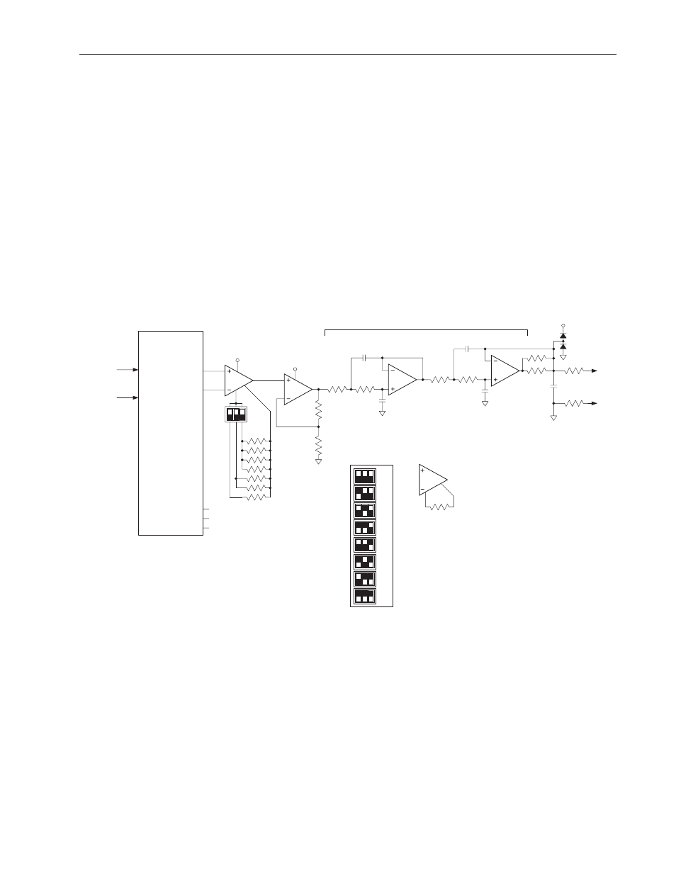
Figure 17
Scaled Analog Output for RTD Board
Digital I/O
The digital outputs are isolated with solid state relays. The outputs are
internally short circuit protected. The digital input is optically isolated.
Microcontroller Software
A microcontroller monitors three DIP switches to determine the operational
mode of the RTD board. A single “Mode” switch determines whether the
board uses an internal timebase or the digital input as a clock to step
through the eight analog input channels. When using the internal timebase,
the other two DIP switches select one of four clock periods.
Analog Multiplexer
SA (1 of 8)
SB (1 of 8)
A0
A1
A2
DA
DB
NTC/RTD
Sourcing
Analog Out
0-10V
12V
0.01
F
10
10
MAX4194
Instrumentation Amp
Rail-to-Rail
Gain Adjustable
Gain Adjust
DIP Switch Settings, S1
(overall gain)
50K
F
F
100K
100K
F
F
100K
100K
4th Order Low Pass Filter
FC = 16 Hz
Channel
Address
x10
Gain = 1 + 50K/Rg
100K
11.1K
MAX4194
x10
Rg
12V
5V
LMC6484
Quad Op Amp
Railt-to-Rail
x20
x30
x40
x50
x60
x70
x80
up
down
S1