Power wiring – Rockwell Automation 20L PowerFlex 700L Frame 1X Liquid-Cooled Adjustable Frequency AC Drive User Manual
Page 19
PowerFlex 700L Frame 1X Drive Installation Instructions – Publication 20L-IN013A-EN-P – June 2009
19
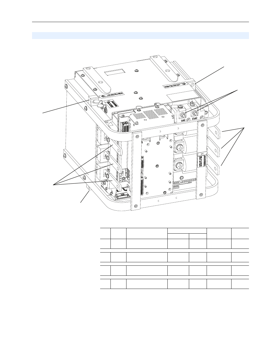
Figure 6
Power Terminal Locations
Table 5
Power Terminal Specifications
Power Wiring
R
➊
S
T
➋
➍
➍
➍
➌
U
T1
V
T2
W
T3
OUTPUT
Item Name
Description
Wire Size Range
(1)
(1)
Maximum/minimum sizes that the terminal block will accept - these are not recommendations.
Recommended
Torque (±10%)
Terminal
Bolt Size
Maximum
Minimum
➊
Input
Power
R (L1), S (L2), and T (L3)
connections
70 mm
2
(2/0 AWG)
50 mm
2
(1 AWG)
7.9 N•m
(70 lb•in)
M6
➋
Output
Power
U (T1), V (T2), and W (T3)
connections
70 mm
2
(2/0 AWG)
50 mm
2
(1 AWG)
3.95 N•m
(35 lb•in)
M5
➌
Brake
Resistor
BR1 (DC Brake +) and BR2
(DC Brake -) connections
35 mm
2
(2 AWG)
25 mm
2
(4 AWG)
3.95 N•m
(35 lb•in)
M5
➍
Ground
PE and motor ground
connections
70 mm
2
(2/0 AWG)
50 mm
2
(1 AWG)
7.9 N•m
(70 lb•in)
M6
- 20P PowerFlex DC Drive - Frame D Bimetal Thermostat (10 pages)
- 1336S_F_T_E_R F Frame Snubber Resistor Repl. (6 pages)
- 22-COMM PowerFlex 4-Class DSI (Drive Serial Interface) Network Communication Adapter (4 pages)
- 8-545 Plug In Solid State Relay (2 pages)
- 20-HIM-B1 PowerFlex 7-Class HIM Bezel (DPI) (4 pages)
- 100 Contactors with DC Coil (1 page)
- 100 Contactors with DC Coil (2 pages)
- 20P PowerFlex DC Drive - Frame D Switching Power Supply Circuit Board (6 pages)
- 140G-MTFx_MTHx_MTIx_MTKx Trip Unit Installation-140G-M (6 pages)
- 45BRD Analog Laser Sensor (4 pages)
- 20D Multi-Device Interface Option Board for PowerFlex 700S Drives (20 pages)
- 56RF RFID 18 mm Cylindrical Transceiver (2 pages)
- 42KC Miniature Rectangular: 5V DC Version (2 pages)
- 20P PowerFlex DC Drive - Frame A Switching Power Supply Circuit Board (16 pages)
- 21P-MISC-A-TP-2 Transition Tube Kit #C19-6/7 For PowerFlex 755 w/OEM Liquid Cooling Fr 6/7 Drive (2 pages)
- 42BT Background Suppression Sensor (3 pages)
- 42CB High Speed 18mm Cylindrical (4 pages)
- 140EX-JE2_JE3 Molded Case Circuit Breaker (4 pages)
- 140G-K-EAM1A Early Make Aux Contact for Rotary Handle Oper Mech-140G-K (3 pages)
- 140G-K-EAM1A Early Make Aux Contact for Rotary Handle Oper Mech-140G-K (1 page)
- 20-HIM-A6 PowerFlex (Human Interface Module) (74 pages)
- 42CF General Purpose 12mm Cylindrical (4 pages)
- 20D PowerFlex 700S Phase II Drive Frames 1...6 (80 pages)
- 140EX-HE1_HE2 Molded Case Circuit Breaker (4 pages)
- 140EX-HE1_HE2 Molded Case Circuit Breaker (6 pages)
- 20B PowerFlex 700 Custom Firmware - Pump Off (12 pages)
- 20-WIM-N4S DPI Wireless Interface Module (92 pages)
- 140U H-Frame Circuit Breaker Fixed and Adjustable Thermal Trip (7 pages)
- 140U H-Frame Circuit Breaker Fixed and Adjustable Thermal Trip (2 pages)
- 60-2619, 42JS Swivel/Tilt Mounting Bracket (1 page)
- 22A PowerFlex 4/40/400 Flange Mount (4 pages)
- 45MLA Controller Installation Instructions (16 pages)
- 20P PowerFlex DC Drive - Cooling Fan for Frame A Drives Above 73A at 230V 460V AC (6 pages)
- 42JS Series 7000 to 42JS VisiSight Replacement Kit (2 pages)
- 22A PowerFlex 4-Class HIM Bezel (DSI) (4 pages)
- 42CS Stainless Steel Photoelectric Sensors (4 pages)
- 20L-LL PowerFlex 700L Liquid-to-Liquid Heat Exchanger (40 pages)
- 20P PowerFlex DC Drive - Frame B SCR Modules (20 pages)
- 22B PowerFlex 40 Quick Start FRN 5.xx - 6.xx (22 pages)
- 22B PowerFlex 40 Quick Start FRN 5.xx - 6.xx (161 pages)
- 22F PowerFlex 4M Input RFI Filters (2 pages)
- 45LFM Capacitive Label Sensor (4 pages)
- 140G-Rx Installation Instruction-140G-R (2 pages)
- 140G-Rx Installation Instruction-140G-R (29 pages)
- 22C PowerFlex 400 AC Drive Quick Start - FRN 1-4.xx (28 pages)