Rockwell Automation 20L PowerFlex 700L Frame 1X Liquid-Cooled Adjustable Frequency AC Drive User Manual
Page 26
PowerFlex 700L Frame 1X Drive Installation Instructions – Publication 20L-IN013A-EN-P – June 2009
26
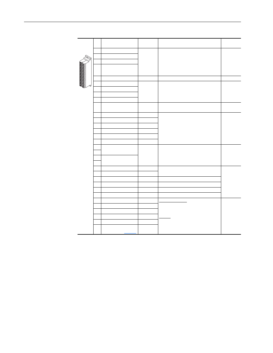
Table 9
Vector Control Option I/O Terminal Designations
No. Signal
Factory
Default
Description
Related
Parameters
1
Analog In 1 (–)
(1)
(2)
Isolated
(3)
, bipolar, differential,
±
10V/
0…20 mA, 11 bit and sign. For 0-20 mA, a
jumper must be installed at terminals 17
and 18 (or 19 and 20). 88k ohm input
impedance when configured for volt and
95.3 ohm for current
320… 327
2
Analog In 1 (+)
(1)
3
Analog In 2 (–)
(1)
4
Analog In 2 (+)
(1)
5
Pot Common
—
For (+) and (–) 10V pot references
6
Analog Out 1 (–)
(2)
Single-ended bipolar (current output is not
bipolar),
±
10V/0…20 mA, 11 bit and sign,
Voltage mode - limit current to 5 mA.
Current mode - max. load is 400 ohms.
340…347
7
Analog Out 1 (+)
8
Analog Out 2 (–)
9
Analog Out 2 (+)
10
HW PTC Input 1
—
1.8k ohm PTC, Internal 3.32k ohm pull-up
resistor
238, 259
11
Digital Out 1 – N.C.
(4)
Fault
Max. Resistive Load:
240V AC/30V DC – 1200VA, 150 W
Max. Current: 5 A, Min. Load: 10 mA
Max. Inductive Load:
240V AC/30V DC – 840VA, 105 W
Max. Current: 3.5 A, Min. Load: 10 mA
380…391
12
Digital Out 1 Common
13
Digital Out 1 – N.O.
(4)
NOT Fault
14
Digital Out 2 – N.C.
(4)
NOT Run
15
Digital Out 2/3 Com.
16
Digital Out 3 – N.O.
(4)
Run
17
Current In Jumper
(1)
–
Analog In 1
Placing a jumper across terminals 17 and
18 (or 19 and 20) will configure that
analog input for current.
320…327
18
19
Current In Jumper
(1)
–
Analog In 2
20
21
–10VDC Pot Ref.
—
2k ohm minimum load
22
+10VDC Pot Ref.
—
23
HW PTC Input 2
—
See above
24
+24VDC
(5)
—
Drive-supplied logic input power
(5)
25
Digital In Common
—
26
24V Common
(5)
—
Common for internal power supply
27
Digital In 1
(6)
Stop - CF
115V AC, 50/60 Hz - Opto isolated
Low State: less than 30V AC
High State: greater than 100V AC, 5.7 mA
24V DC - Opto isolated
Low State: less than 5V DC
High State: greater than 20V DC, 10 mA
DC Digital Input Impedance: 21k ohm
361…366
28
Digital In 2
(6)
Start
29
Digital In 3
(6)
Auto/Man.
30
Digital In 4
(6)
Speed Sel 1
31
Digital In 5
(6)
Speed Sel 2
32
Digital In 6/Hardware
Enable
(6)
Speed Sel 3
(1)
Important: 0…20 mA operation requires a jumper at terminals 17 and 18 (or 19 and 20). Drive damage may occur if
jumper is not installed.
(2)
These inputs/outputs are dependant on a number of parameters (see “Related Parameters”).
(3)
Differential Isolation - External source must be maintained at less than 160V with respect to PE. Input provides high
common mode immunity.
(4)
Contacts in unpowered state. Any relay programmed as Fault or Alarm will energize (pick up) when power is applied to
drive and deenergize (drop out) when a fault or alarm exists. Relays selected for other functions will energize only when
that condition exists and will deenergize when condition is removed.
(5)
150 mA maximum load designed to power digital inputs only. Not present on 115V versions.
(6)
A 10k ohm, 2 watt burden resistor must be installed on each digital input when using a triac type device. The resistor is
installed between each digital input and neutral/common.
1
16
32