Rockwell Automation 20L PowerFlex 700L Frame 1X Liquid-Cooled Adjustable Frequency AC Drive User Manual
Page 23
PowerFlex 700L Frame 1X Drive Installation Instructions – Publication 20L-IN013A-EN-P – June 2009
23
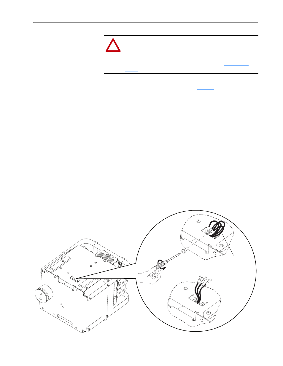
The power jumpers PE-A, PE-C, PE-D, and PE-E are factory connected to
ground using one of the two screws shown in
Figure 9
. Jumpers PE-D and
PE-E must remain connected.
To connect or disconnect the drive’s protective MOVs and common mode
capacitors, refer to
Table 7
and
Figure 9
. Then:
1. Remove the appropriate screw(s) from the drive flange that connect the
wire(s).
2. Cut the lugs off the ground wire(s) to be disconnected. Apply wire nuts
to the end(s) of the disconnected wires.
3. Tie wrap the disconnected ground wires to keep them away from any
electrical connections.
4. Gather together the wire lugs of the remaining ground wires to be
connected. Using the screw(s), fasten the ground wires to the drive
flange. Torque to 3.2 N
•
m (28 lb
•
in).
5. Tuck the wires back into the drive flange.
Figure 9
Protective Circuit Connections for Grounded Drive Distribution Systems
!
ATTENTION: To avoid an electric shock hazard, verify that the
voltage on the bus capacitors has discharged before connecting/
disconnecting the MOV, EMI Snubber Board, and common mode
capacitor wires. Measure the DC bus voltage at the DC+ and
DC– Test Pt. sockets on the drive (see item 9 in
for location). The voltage must be zero.
U
T1
V
T2
W
T3
OUTPUT
Labeled ground
wires PE-A, PE-B,
PE-C, PE-D, and
PE-E