Rockwell Automation 20L PowerFlex 700L Frame 1X Liquid-Cooled Adjustable Frequency AC Drive User Manual
Page 36
PowerFlex 700L Frame 1X Drive Installation Instructions – Publication 20L-IN013A-EN-P – June 2009
36
When the “Mode” switch is up (open) the board uses the digital input as an
enable/reset. When the board’s digital input is inactive (open or ground), the
analog output is held at the first channel. When the digital input is active
(24V), the microcontroller sequentially cycles through the eight temperature
sensor channels. Each channel is available at the analog output for the
selected period of time. After the eighth channel is completed, the cycle
begins again with the first channel. Deactivating the digital input will
asynchronously reset the sequence back to the first channel. The “Time”
jumpers/DIP switches select one of four time periods between temperature
sensor channels.
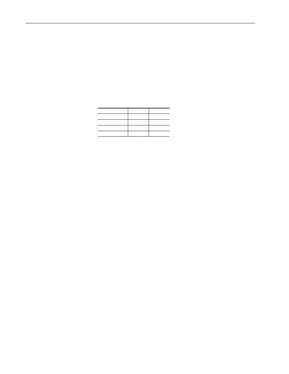
Table 13 Microcontroller Settings
When the “Mode” switch (S2-1) is down (closed), the board uses the digital
input as an external clock to sequentially cycle through the eight
temperature sensor channels. The analog output channel advances with both
the rising and falling edges of the digital input. In both modes, the active
channel is output as a 3-bit binary address on the RTD board’s digital
outputs. An inactive output (open) indicates a “0.” When using the digital
input as an external clock, it may be necessary to monitor the address lines
in order to maintain synchronization with the controller. When using the
internal clock mode, the digital outputs may be ignored to reduce the
required number of I/O. In either mode, the board’s digital input is
debounced with a period of 50 milliseconds.
Time Period
S2-2
S2-3
1 second
Down
Down
10 seconds
Up
Down
30 seconds
Down
Up
60 seconds
Up
Up