5motor control (mctrl) – Lenze E84DSxxx User Manual
Page 105
Lenze · 8400 protec StateLine · Reference manual · DMS 4.2 EN · 03/2013 · TD05
105
5
Motor control (MCTRL)
5.1
Motor selection/Motor data
_ _ _ _ _ _ _ _ _ _ _ _ _ _ _ _ _ _ _ _ _ _ _ _ _ _ _ _ _ _ _ _ _ _ _ _ _ _ _ _ _ _ _ _ _ _ _ _ _ _ _ _ _ _ _ _ _ _ _ _ _ _ _ _
Preconditions
The motor parameters listed in the table below are excluded from automatic identification and
must therefore be adapted to the used motor before motor parameter identification is carried out
(see motor nameplate).
Furthermore, the available motor cable must be specified in terms of length and cross-section:
Duration & sequence of the motor parameter identification
The duration of the motor parameter identification is approx. 30 s. The following steps are carried
out during this time:
1. The motor stator resistance (
) is measured.
2. The inverter error characteristic is measured.
3. The motor stator leakage inductance (
) is measured.
4. The motor magnetising inductance (
) and the motor rotor resistance (
measured.
5. The motor magnetising current
) is measured.
6. The V/f base frequency (
) is calculated.
7. The slip compensation (
) is calculated.
8. The V
min
) is detected.
Optimising motor parameter identification
For the measurement of the required variables, the motor is energised via the controller terminals
U, V and W during the motor parameter identification.
The corresponding current controller can be set via the following parameters:
In the Lenze setting, the current controller is preset in such a way that an optimum controller
behaviour is obtained for a motor with power adaptation to the inverter.
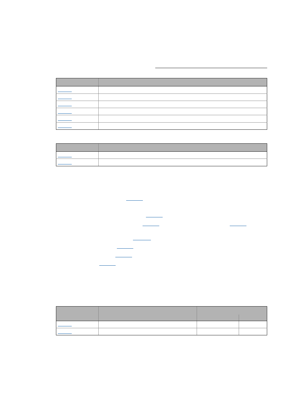
Parameter
Info
Rated motor power
Rated motor speed
Rated motor current
Rated motor frequency
Rated motor voltage
Motor cos ϕ
Parameter
Info
Motor cable length
Motor cable cross-section
Parameter
Info
Lenze setting
Value Unit
Vp current controller
7.00 V/A
Ti current controller
10.61 ms