2 control panel – INFICON Guardian EIES Controller User Manual
Page 58
3 - 6
IP
N 07
4-
51
7-
P1
D
Guardian Co-Deposition Controller Operating Manual
Layer Time: The accumulated time for this layer. Resets to 0 if the layer is stopped.
Phase: The current layer phase. Phases consist of pre conditioning (Ramp1,
Soak1, Ramp2, Soak2), Shutter Delay, Deposition, and post conditioning (Idle
Ramp). Additional phases, such as Stopped, Layer Stopped and Filter change are
also displayed.
Phase Time: Phase time is shown as ElapsedTime/TimeRemaining.
Progress: A graphical display of the percent complete for the current phase.
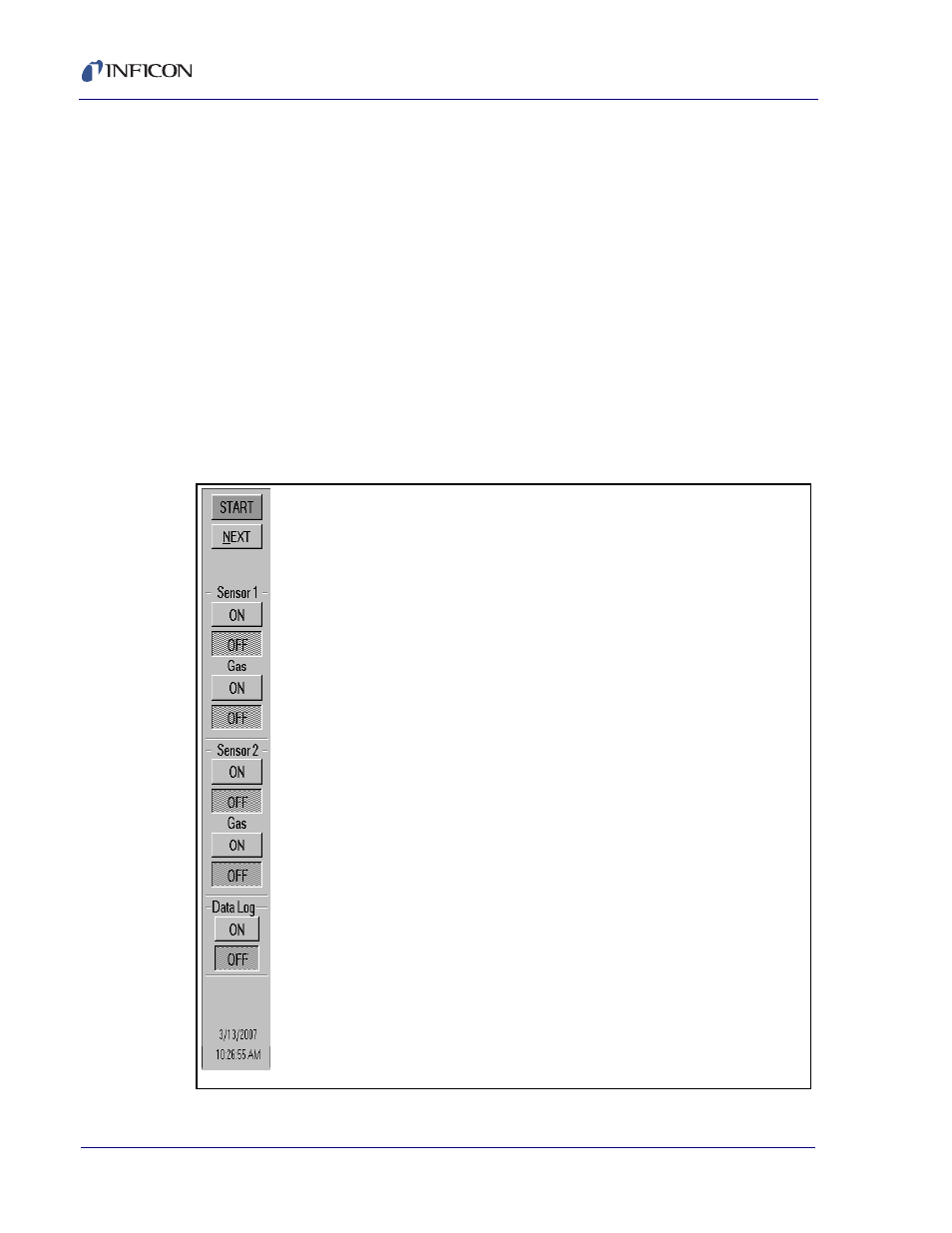
3.3.2 Control Panel
NOTE: To avoid accidental activation of the Start/Stop, Auto/Man, and Emission
controls you may need to press and hold the Ctrl key while clicking the
control. This feature can be disabled on the Display tab of the Edit System
screen.
Figure 3-7 Control Panel
Start/Stop: Click Start to run the process. The Start control is disabled
if there are no communications with the EIES controller. When the
process is running, the top control displays Stop. Click Stop to stop the
process and set all outputs to 0. Press Start again to restart the layer.
Next: When the process is stopped, click Next to move to the next
process layer. The selected layer is displayed in the Status panel.
When Start is clicked, the process will start at the selected layer.
Reset: When a process is stopped, click Reset to abort the process
and reset the selected layer to 1.
Emission Controls: When first started, both the EIES instrument and
this program turn both sensors Off. Be sure Emission On is selected
when running the process or no EIES readings will occur. Turn sensor
Emission Off when not in use, or anytime the pressure exceeds 5x10⁻⁴
Torr. When Gas Compensating sensors are used, both the main
sensor and the Gas sensor should be on. The main and gas sensor
can be turned on/off simultaneously by holding the
clicking the main sensor on/off.
When emission is On, the sensor's emission current is displayed with
a green background. If the leakage current reaches 70% of the
maximum allowed value, the background turns yellow. Maximum
Leakage is set in the Edit System dialog box, Sensor tab.
DataLog Control: Turns disk data logging on/off. Data is logged only
while the process is running. Edit data logging options in the File,
DataLog menu.