2 eies controller, 3 eies sensor – INFICON Guardian EIES Controller User Manual
Page 16
1 - 2
IP
N 07
4-
51
7-
P1
D
Guardian Co-Deposition Controller Operating Manual
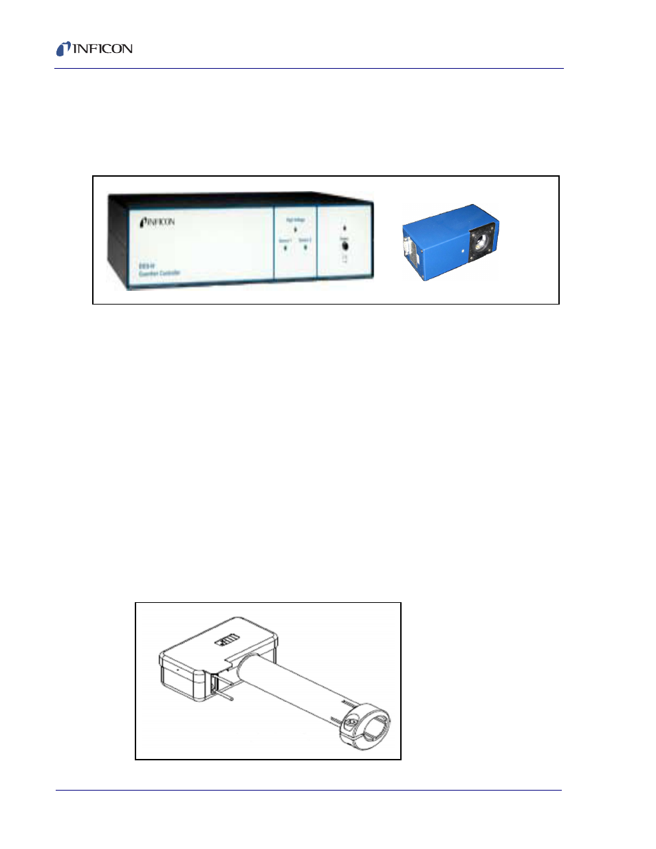
1.2 EIES Controller
The EIES-IV Guardian Controller serves as the interface between the EIES
sensor(s) and detector(s), the evaporation power supply, and the computer running
the EIES software. See
.
Figure 1-2 Guardian Controller with Detector
The controller supplies power to both the filament of the sensor assembly and to
the detector modules. It communicates with each detector, passing the detector
measurements to the computer running the EIES program. Control voltages for
evaporation power supplies are also generated in the controller. Finally, relays and
digital inputs to operate shutters, etc., are included in the controller.
The controller is operated from a computer running the EIES software via RS-232
or Ethernet. Other than a power switch and a few status LEDs, there are no
operator controls on the EIES-IV Guardian Controller.
1.3 EIES Sensor
In the sensor assembly, see
, high-energy electrons from a hot filament
excite the valence electrons of the deposited material. These excited electrons
emit light at wavelengths that are characteristic of each material. A light tube
conducts the light to a feedthrough with a viewport, where it is measured by the
Photomultiplier Tube (PMT) of the detector module(s). A single sensor, see
, can be used to create emissions from multiple materials.
Figure 1-3 EIES Single Sensor 016-400-G1