4 initial setup, 1 power-up sequence, 2 communications – INFICON Guardian EIES Controller User Manual
Page 42
2 - 18
IP
N 07
4-
51
7-
P1
D
Guardian Co-Deposition Controller Operating Manual
2.4 Initial Setup
Connect the Guardian controller rear panel RS-232 connector to your computer
serial port using a straight through DB-9 Male-Female cable (IPN# 068-0464 in
Guardian ship kit). Connect your detector module(s) to the rear panel of the
Guardian controller with 782-505-065 (3 m) or 782-505-065-40 (10 m) cable(s).
2.4.1 Power-up Sequence
1
Press the power switch on the Guardian controller.
2
Start the EIES Software.
3
Turn on the evaporation power supplies.
2.4.2 Communications
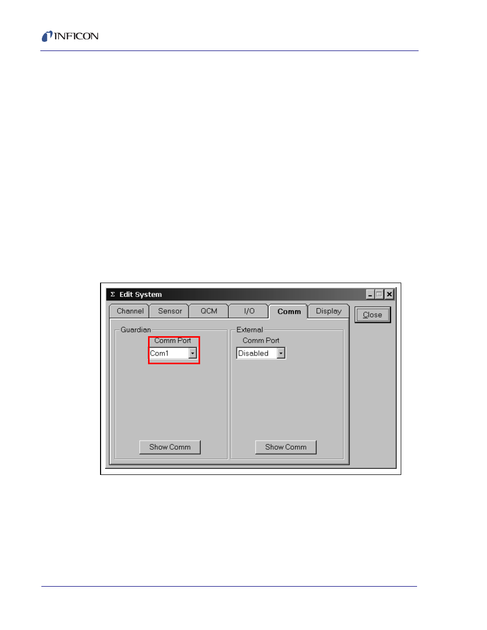
If a Comm Error message appears on the main screen status line, click Edit >>
System, and the Comm tab. Select the Comm Port used for communications with
the Guardian controller.
Figure 2-17 Selecting Comm Port
If you are connecting to the Guardian controller by Ethernet, select Ethernet in the
Comm Port drop-down. Enter the Port (typically 2101) and address (default factory
setting is 192.168.1.200) .
When the proper communications parameters are entered and communication is
successfully established, the main screen Comm Error message will disappear and
the screen will show Version x.xx where x.xx is the firmware version in the
controller.