6 controller installation, 1 digital i/o, Guardian co-deposition controller operating manual – INFICON Guardian EIES Controller User Manual
Page 109: Figure 4-16 rear panel, Figure 4-17 inputs and relays connector rear view
4 - 17
IP
N 07
4-
51
7-
P1
D
Guardian Co-Deposition Controller Operating Manual
4.6 Controller Installation
Mount the controller in a location that allows easy wiring access to the EIES sensor
and detector assemblies. The controller may be placed up to 25 feet from the EIES
computer.
4.6.1 Digital I/O
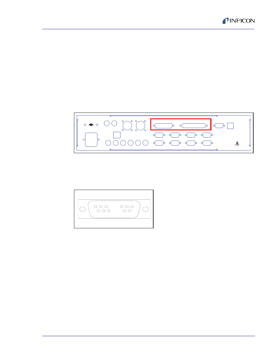
Two connectors on the rear panel provide digital inputs and relay output
connections. Connect the Emission Interlock connector or equivalent to the
INPUTS connector as described at
Emission Interlock.
Figure 4-16 Rear Panel
The digital inputs are supplied on a 25-pin male D-sub connector.
Relay outputs are on a 37-pin male D-sub connector.
shows the
connector pin numbering, as seen from the rear of the Guardian controller.
Figure 4-17 Inputs and Relays Connector Rear View
On both connectors, pin one is in the upper left corner. The last pin (25 or 37) is in
the lower right corner.
100-240VAC
100VA
ETHERNET
SENSOR 1
CONTROL OUTPUTS
1
2
3
4
5
6
MODULE 1
MODULE 3
MODULE 5
MODULE 7
MODULE 8
MODULE 6
MODULE 4
MODULE 2
SENSOR 2
INPUTS
RELAYS
HAND
CONTROL
RS-232
Guardian Controller
Serial No.
1
13/19
14/20
25/37