2 pneumatic installation, 3 electrical installation – Festo DRRD-12 ... 63 User Manual
Page 22
DRRD-12 ... 63
22
Festo – DRRD-12 ... 63-Z6 – 1310b English
5.2
Pneumatic installation
•
If necessary, remove the covers in the pneu-
matic ports.
To adjust the swivel speed:
•
Use the GRLA one-way flow control valves.
These are screwed directly into the com-
pressed air supply ports.
Fig. 5
For vertical installation and eccentric loads:
•
Use the controlled check valve HGL or a compressed air spacer compensation reservoir VZS.
In this way you can prevent the effective load from sliding down suddenly if there is a sudden pres-
sure drop.
5.3
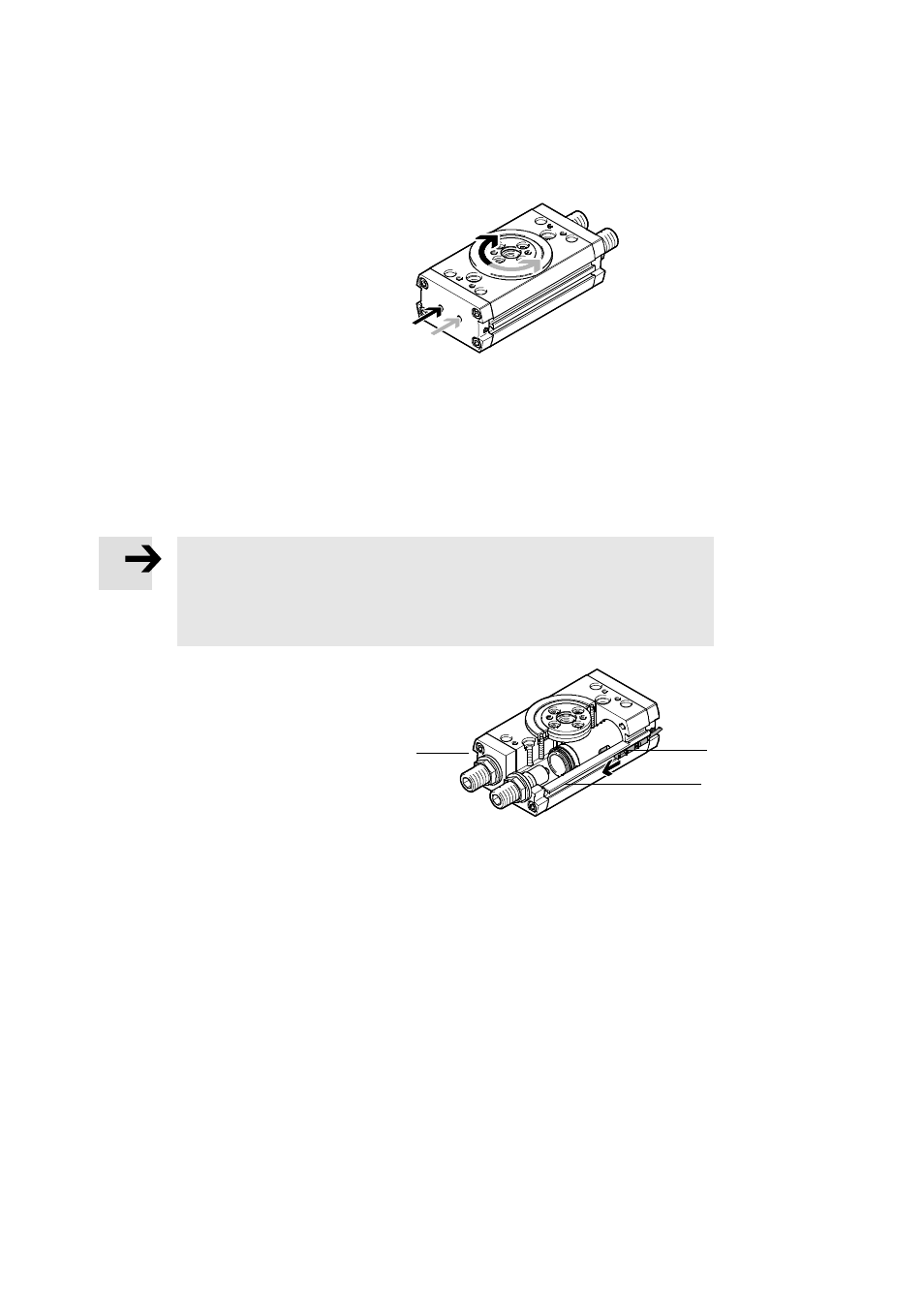
Electrical installation
Note
Multiple switching cycles of cylinder switches are possible, dependent on the design.
•
Make sure the cylinder switches are always set to the first switching point.
To do this, push the cylinder switch (A) in from the slot end where the piston to be
sensed is located until the first switching occurs.
•
Place the cylinder switches for sensing the end
positions into the slots
9.
Sensing can be conducted with inductive prox-
imity sensors with the help of the external
sensing kit (
10 Accessories).
9
Fig. 6
(A)
9