Festo DRRD-12 ... 63 User Manual
Page 21
DRRD-12 ... 63
Festo – DRRD-12 ... 63-Z6 – 1310b English
21
3. Feed the appropriate lines through the hollow
drive shaft, if necessary, or use the variant
with energy throughfeed.
The shaft opening for wiring has the following
dimensions (
Tab. 2).
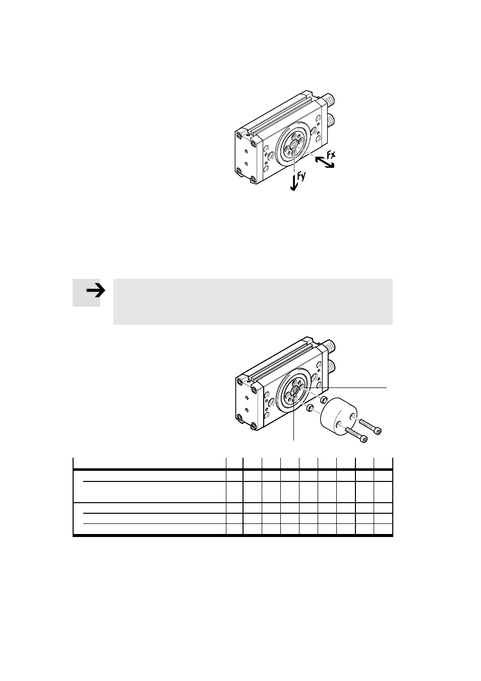
4. When mounting the moving mass, make sure
that the following specifications are observed:
–
installation without tilting
–
permissible radial force Fy
–
permissible axial force Fx
–
permissible mass moment of inertia
–
a structure that is as rotationally symmet-
rical as possible.
Fig. 3
The mass moment of inertia of the payload should be calculated. Lever arms, cantilevers and
masses should be considered in the calculation (maximum permissible values
Catalogue
specifications, www.festo.com/catalogue).
Note
If there are demanding requirements for concentricity of the components on the flanged
shaft:
•
Use the middle centring hole
4 as well as one of the 4 existing centring holes.
5. Secure the effective load to the drive flange at
the mounting interface
aA by using at least
two screws positioned opposite one another
and centring sleeves.
The tightening torque is summarised in the
following table (
Tab. 2).
aA
Fig. 4
4
Size
12
16
20
25
32
35
40
50
63
Shaft opening
4
[mm]
5
8
8
10.5 10.5 10.5 21
21
21
Centring sleeve ZBH for middle
centring hole
[mm]
7
12
12
15
15
25
25
25
25
Screw for thread at
aA
M3
M4
M4
M5
M6
M6
M6
M8
M10
Centring sleeve ZBH
[mm]
5
7
7
9
9
9
9
12
15
Tightening torque
[Nm]
1.2 3
3
6
10
10
10
20
40
Tab. 2