Stabil-trak system – SkyTrak 10054 User Manual
Page 358
364
SECTION 10
Stabil-TRAK System
The following information explains the difference between a typical
telescopic handler and the benefits that the Stabil-TRAK System
provides.
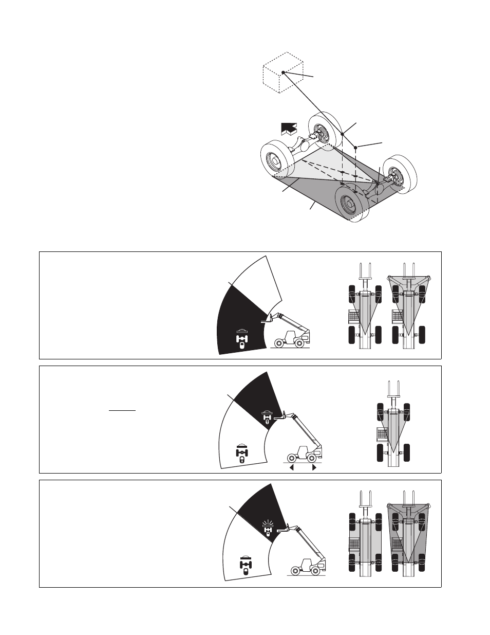
Most telescopic handlers operate within a 3 point stability triangle, as
defined by points A, B, and C in the illustration to the right. Point 1 in
the illustration represents the center of gravity of an unloaded
vehicle. The load has its own center of gravity indicated by Point 3.
When the vehicle is loaded, the vehicle and the load become one
mass having a combined center of gravity represented by Point 2.
As the boom is lowered or extended, Point 2 will move forward in the
3 point stability triangle, or backward in the stability triangle as the
boom is raised. Point 2 can also move left or right toward the edges
of the stability triangle if the frame is tilted. As long as Point 2
remains within the boundaries of the 3 point stability triangle, the
vehicle will remain stable. If Point 2 ever goes beyond the boundaries
of the stability triangle, the vehicle can tip over.
In the locked mode, the exclusive Stabil-TRAK System provides a
4 point stability rectangle by positively locking the frame to the rear
axle through the stabilizer cylinder. The vehicle is then supported at
four points, A, B, D, and E. While in the locked mode, it is clear that
Point 2 will remain within the entire boundary of the 4 point Stabil-
TRAK stability rectangle, giving the operator more flexibility in
positioning a load.
The Stabil-TRAK System functions in the following three modes:
This illustration shows the
increase in stability with
the Stabil-TRAK System.
Load
Center of
Gravity
Combined
Center of
Gravity
Vehicle
Center of
Gravity
3 Point
Stability
Triangle
3
FRONT
2
1
B
A
C
D
E
PH0712
Stabil-TRAK
4 Point Stability
Rectangle
Free Pivot Mode
With the boom below 40°, the Stabil-TRAK System is in
the free pivot mode and the rear axle is allowed to pivot
freely.
The frame tilt functions normally, with or without the
outriggers down.
Angle Of
Stabil-TRAK
Activation
40°
3 Point Stability
Outriggers Down
FREE PIVOT
MODE
Stabil-TRAK
Light "OFF"
PH0721
PH0770
PH0750
Final Positioning Mode
With the boom above 40°, and the vehicle traveling, the
Stabil-TRAK System is in the final positioning mode. In
this mode the rear axle is unlocked and is allowed to
pivot, but will respond SLOWLY to changes in terrain.
The frame tilt functions normally in this mode.
40°
Angle Of
Stabil-TRAK
Activation
FINAL
POSITIONING
MODE
Stabil-TRAK Light
"OFF"
Travel
FREE PIVOT
MODE
Stabil-TRAK
Light
"OFF"
3 Point Stability
PH0731
PH0750
Locked Mode
With the boom above 40°, and one or more of the
following functions activated, the Stabil-TRAK System is
in the locked mode and the rear axle is locked so it is
rigid with the frame.
• Engaging the Emergency Brake Switch
• Placing the Travel Select Lever in NEUTRAL
• Depressing and holding the Service Brake Pedal
The frame tilt functions slower than normal in this mode,
with or without the outriggers down.
40°
Angle Of
Stabil-TRAK
Activation
FREE PIVOT
MODE
Stabil-TRAK
Light
"OFF"
4 Point Stability
Outriggers Down
PH0780
PH0760
LOCKED
MODE
Stabil-TRAK
Light "ON"
PH0741
Rev. 2/00