Class1 FoamLogix 2.1A & 1.7AHP REV D User Manual
Page 94
FoamLogix, Model 2.1A and 1.7AHP Class “A”
Electronic Foam Proportioning Systems
94
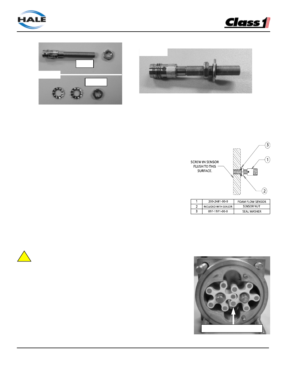
STEPS 8-9
STEP 7
Keep
Discard
8. Thread the new foam flow sensor nut onto the sensor about 1/2” (12mm).
9. Thread (do NOT push) the new seal washer onto the foam flow sensor about 1/2” (12mm).
• This seal washer should be silver in color, with a black, rubber seal on the inner diameter.
10. Thread the new foam flow sensor into the brass cover by hand, so that the sensor tip is flush with the inside face of the
cover.
• DO NOT USE LOCTITE OR THREAD SEALANT ON THE
FOAM FLOW SENSOR.
• Use a straight edge or flat object to verify the flush position.
• TIP – When installing the foam flow sensor, it may be easier to lay
the brass cover on a flat surface (carefully remove o-ring), and check
for flush position after the nut is secure.
11. While holding the new foam flow sensor, lightly tighten the nut with
the 5/16” wrench to set the seal washer on the outer face of the brass
cover.
12. Verify that the sensor tip is flush with the inner surface and torque the
jam nut to a maximum 10.0 in-lb (1.1 N-m).
• Do not bend or over-tighten the sensor.
• Use a fine stone to lightly remove any flashing that might stick out after tightening the sensor nut.
13. Remove and inspect the two plastic rotors inside the flowmeter assembly for cracks, burrs, etc.
14. Inspect the inner housing for debris, metal shavings, etc. and remove as necessary.
15. Reinstall both rotors, making sure that each spins freely without binding.
!
•When installed, the flush end of the metal targets in the rotors must face out,
toward the foam flow sensor.
16. Reinstall the o-ring (if necessary) and reattach the brass cover and the bracket
with the six (6) nuts.
• Tighten all nuts securely and torque to a maximum 6.5 ft-lb (8.5 N-m). Use a
criss-cross torque pattern on the four brass housing nuts and bolts.
17. Reattach foam lines and foam flow sensor harness.
18. Apply system power to the FoamLogix system and recalibrate the system per the
user manual instructions.
STEP 15
Rotor targets must face sensor