Class1 115355 - ITL 4LT with 1-wire and CAN COM 113739 114378 - Page User Manual
Class1 For the car
Intelli-Tank Display with 1-wire & CAN
Quick Start Guide
INSTALLATION
Mount the unit with the TOP situated up before
applying the label to the display.
WIRING
Master – Only pins 1, 2, 6, 7, 8 are required for a system that
doesn’t use any remote units. If remote units are part of the
system pin 4 (1-wire communication) or pins 4 and 5 (CAN
communications) must be used.
**
See full manual p/n 114356 for detailed information.
Remote – Only pins 1, 2, 4 or 4 and 5 are required for a
remote unit. Pin 4 of the Master and Remote units must be all
tied together.
**
See full manual p/n 114356 for detailed information.
Dim – Apply positive voltage (+VIGN) to Pin 3 to dim the
display.
PRESSURE TRANSDUCER MOUNTING
Mount the transducer vertically to insure an accurate reading.
MAGNETIC SWITCH ACTIVATION
A magnet is required to activate the
magnetic switches.
Each magnetic switch activation
must occur within 2 seconds of the
last or the password will be reset.
The top two LEDs will light when the
LEFT magnetic switch is activated.
The bottom LED will light when the
RIGHT magnetic switch is activated.
Activate a magnetic switch by using an in-and-out motion starting
from approximately two inches away from the bezel.
Do not use a swiping action.
1 POINT CALIBRATION (FULL)
1.
FILL the tank. Enter the password RLLR LRRL to store the
calibration. Unit flashes top LED twice, then displays FULL
(all LEDs on). Calibration complete.
2 POINT CALIBRATION (EMPTY, FULL)
1.
Enter the password RLLR LLRL to enter 2 point calibration
configuration mode. Unit flashes the two center LEDs twice.
Unit begins cascading (drip) all four LEDs.
2.
Ensure the tank is EMPTY. Activate the RIGHT switch to
store this point. Unit flashes top LED, then lights all four
LEDs.
3.
FILL the tank. Activate the RIGHT switch. Unit flashes top
LED, lights the two center LEDs, then displays FULL (all
LEDs on). Calibration complete.
Make certain that the FULL point used for tank calibration is
approximately 1 inch [2.54 cm] to 2 inches [5.08 cm] from the
physical top of the tank.
Do not calibrate the FULL point with the water level up into the fill
tower.
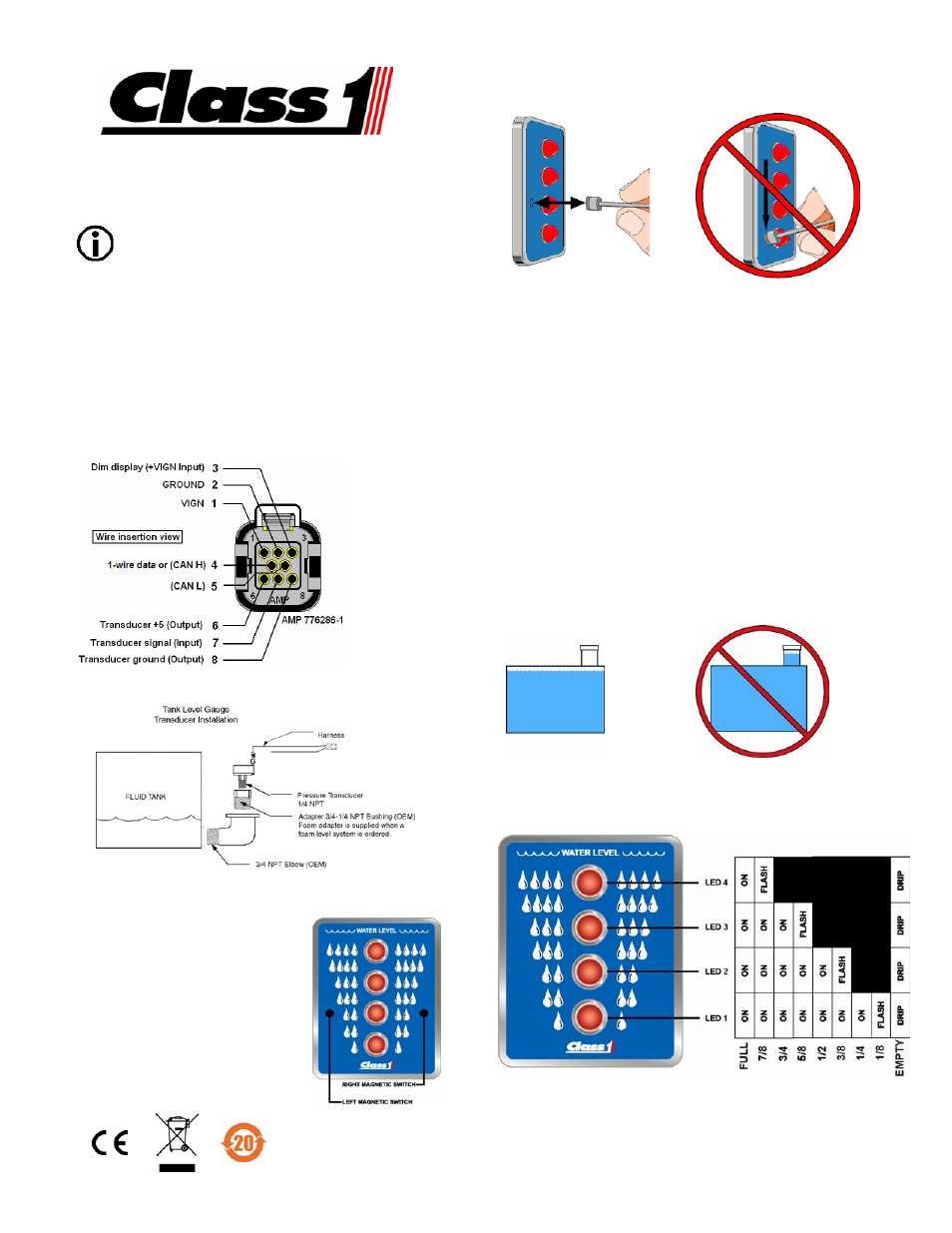
OPERATION
During power up the display will individually cycle on each LED
starting with the bottom LED. The unit will then show current tank
level information.
DRIP = cascades from top (LED 4) to bottom (LED 1), pauses, and repeats.
For detailed operation and troubleshooting consult the full
manual (p/n 114356) available from the Class 1 web site
www.Class1.com
Manual PN 115355 Rev 102307