Class1 117155 - TPG Governor - 117685 User Manual
Total pressure governor (tpg) oem quick manual
Total Pressure Governor (TPG)
OEM Quick Manual
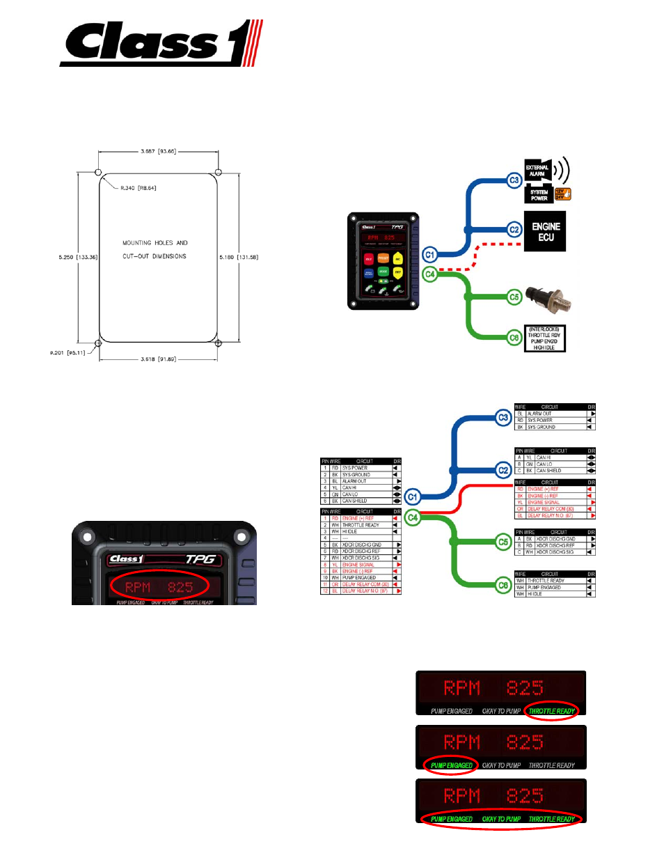
INSTALLATION
Mount the TPG on the operator’s panel with four #10 screws. The
dimensions in the detail below are in inches [millimeters].
WIRING HARNESS
The main system harness (p/n 117666) is comprised of a pair of
harnesses: the power/communication harness (depicted below in
blue) and the signals harness (depicted below in green).
For the analog control option, add harness wires (p/n 117683)
depicted above in red.
PRESSURE TRANSDUCER INSTALLATION
Install the pressure transducer (p/n 113557) on the
discharge side of the pump. The pressure connection is a
¼-18 NPT male port. A ‘T’ fitting can be used to share the
pressure gauge outlet on the discharge manifold.
VERIFY ENGINE RPM
Verify proper J1939 CAN connection to the engine’s ECM by
monitoring the RPM display of the TPG while the engine is
running. The display should show accurate RPM
information.
VERIFY INTERLOCKS
The TPG requires OEM provided interlocks THROTTLE READY and PUMP ENGAGED for proper operation. The TPG utilizes backlit text to
indicate interlock status.
Activate the throttle ready interlock. (Apply system power to pin 2 of connector C5).
Verify the THROTTLE READY text below the display illuminates.
► The TPG will operate in RPM mode only and cannot be changed to pressure mode.
Activate the pump engaged interlock. (Apply system power to pin 10 of connector C5).
Verify the PUMP ENGAGED text below the display illuminates.
► The TPG will not operate in any mode without the THROTTLE READY interlock.
Activate the throttle ready and pump engaged interlocks. (Apply system power to pins 2
and 10 of connector C5).
Verify the PUMP ENAGED, OKAY TO PUMP, and THROTTLE READY text below the
display illuminates.
► The TPG will operate in either mode.