Class1 FoamLogix 2.1A & 1.7AHP REV D User Manual
Page 35
FoamLogix, Model 2.1A and 1.7AHP Class “A”
Electronic Foam Proportioning Systems
35
The diagram provides recommended guidelines for
the installation of system components that handle
water, foam concentrate and foam solu tion. The
sequence in which the plumbing installation is
completed depends on your indi vidual installation.
Water and Foam Solution Plumbing
When installing water and foam solution piping runs,
use best industry practices to install this piping. Use
a suitable pipe sealing compound at all joints.
Check Valve Manifold
Hale pre-made stainless steel foam manifolds
are recommended.
The manifolds are available in kits and elimi nate
the extra labor and leaks from large pipe thread
connections.
The manifolds use 3” (76mm) Victaulic
connections and are available in single or dual
check valve configurations.
Figure 9: “Check Valve Manifold Installation,” on
page 36, shows a typical check valve manifold
installation.
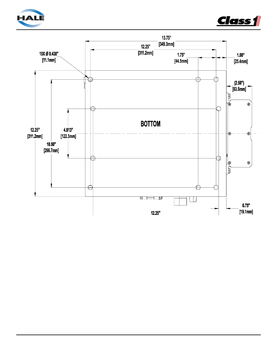
Figure 8: Base Plate Mounting Hole Locations