Class1 Intelli Tank Quick Calibration User Manual
Intelli-tank display quick manual
Intelli-Tank Display
Quick Manual
INSTALLATION
Ensure the unit is mounted with the TOP situated up before
applying the label to the display.
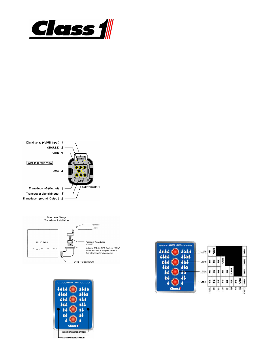
WIRING
The following details assume the 1-wire communication method
is used. For CAN communication information and set-up
please refer to the complete operation manual Class 1 p/n
114356.
Master – Only pins 1, 2, 6, 7, 8 are required for a system that
doesn’t use any remote units. Pin 4 must be used if remote
units are part of the system, and pin 3 should be used if the
display dimming feature is used.
Remote – Only pins 1, 2, 4 are required for a remote unit. Pin
3 should be used if the display dimming feature is used. Pin 4
of the Master and Remote units must be all tied together.
PRESSURE TRANSDUCER MOUNTING
Mount the transducer vertically to insure an accurate reading.
MAGNETIC SWITCH ACTIVATION
Magnetic switch locator.
The top two LEDs will light when the LEFT magnetic switch is
activated.
The bottom LED will light when the RIGHT magnetic switch is
activated.
1 POINT CALIBRATION
A magnet is required to activate the magnetic switches. Each of
the magnetic switch activations must occur within 2 seconds of
the last or the password will be reset.
1.
Make certain the tank is FULL. Enter the password
RLLR LRRL. The unit will respond by flashing the top
LED twice. The unit will then start to normal operation
by displaying FULL (all LEDs on).
2 POINT CALIBRATION
A magnet is required to activate the magnetic switches. Each of
the magnetic switch activations must occur within 2 seconds of
the last or the password will be reset.
1.
Enter the password RLLR LLRL. The unit will respond
by flashing the two center LEDs twice. The unit will then
begin cascading (drip) all four LEDs.
2.
Make certain that the tank is EMPTY and then activate
the RIGHT switch to store that point. The unit will flash
the top LED and then turn on all four LEDs.
3.
Fill the tank and then activate the RIGHT switch. The
unit will respond by flashing the top LED then lighting the
two center LEDs and then reverting to normal operation
by displaying FULL (all LEDs on).
CONFIGURING DIM SETTING
Use a magnet and enter the dim level configuration password
RLLR LLLR.
All LEDs will turn on at the last set dim level. Activate the RIGHT
switch to change the brightness. (Releasing the RIGHT switch
and then reactivating will change the direction of the brightness.)
Activate the LEFT switch when the desired level is attained.
OPERATION
During power up the display will individually cycle on each LED
starting with the bottom LED. The unit will then show current tank
level information.
DRIP = cascades from top (LED 4) to bottom (LED 1), pauses, and repeats.
For a detailed operation and troubleshooting
manual (p/n 114356) visit www.Class1.com
Manual PN 109395 Rev050906