Class1 FoamLogix 2.1A & 1.7AHP REV D User Manual
Page 41
FoamLogix, Model 2.1A and 1.7AHP Class “A”
Electronic Foam Proportioning Systems
41
Th
e hose from the foam tank to the strainer must
have adequate wall stiffness to with stand the
vacuum of the foam pump while it is operating (23”
[584 mm] Hg and 50 PSI [3 BAR], Kuriyama, Kuri-
tec K-3130 or K-7130 series or equal).
After the foam pump is mounted on the apparatus,
connect the PVC hose provided to the strainer inlet.
Install the clear plastic hose from the foam tank
outlet to the inlet of the strainer/valve assembly.
The inlet is on the valve end. Wetting the ends
of the hose and fittings makes the installation on
the hose fittings easier.
CAUTION!
MAKE SURE THE FOAM TANK AND FOAM CON-
CENTRATE SUCTION HOSES ARE CLEAN BE FORE
MAKING FINAL CONNECTION TO FOAM PUMP. IF
NECESSARY FLUSH TANK AND HOSES PRIOR TO
MAKING CONNECTION.
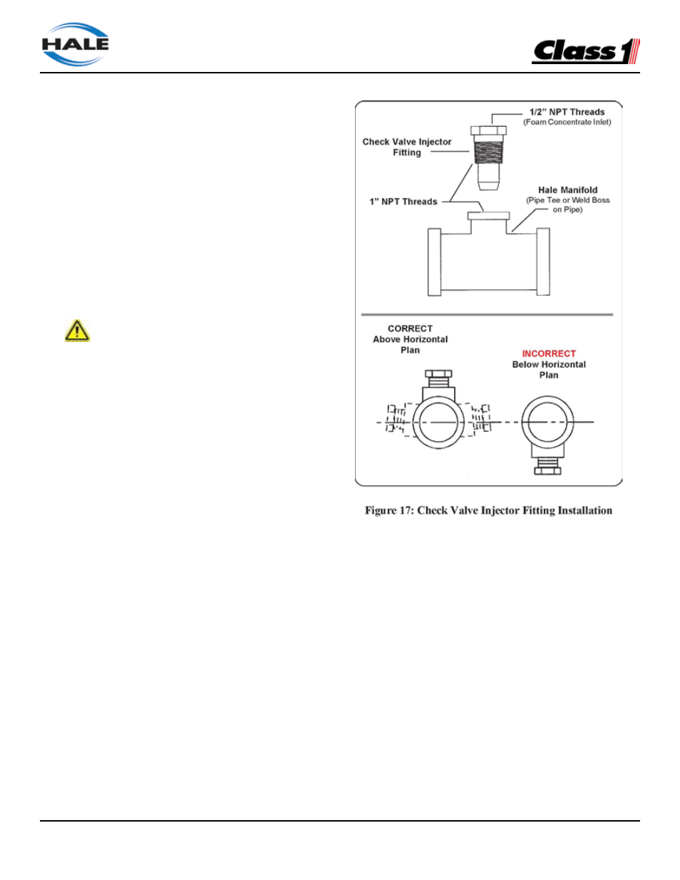
Check Valve/Injector Fitting
The Hale check valve/injector fitting, supplied
with the Hale FoamLogix system, meets NFPA
requirements for a non-return device in the foam
injection system. It prevents back flow of water into
the foam concentrate tank.
When properly installed the brass and stain-
less steel construction check valve/injector fitting
ensures foam concentrate is injected into the
center of the water flow for better mixing.
Note: Always position the check valve/ injector fitting
at a horizontal or higher angle to allow water to drain
away from the fitting. (See Figure 17: “Check Valve
Injector Fitting Installation.”) This avoids sediment
deposits or the formation of an ice plug.
The check valve/injector fitting MUST be mounted
in a location that is common to all discharges which
require foam concentrate. (See Figure 18: “Injection
and bypass Hose Connection”)
The Hale FoamLogix system DOES NOT permit
a separate injection point for each foam capable
discharge.
The check valve/injector fitting has – 1” NPT
(25.4mm) threads on the outside, to fit into the 1”
NPT threaded connection on the Hale mini manifold
a pipe tee, or a 1” NPT weld fitting installed in the
discharge piping of the fire pump. (See Figure 17:
“Check Valve Injector Fitting Installation.”)