System installer start-up, Initial system power check, Initial system check – Class1 FoamLogix 2.1A & 1.7AHP REV D User Manual
Page 49
FoamLogix, Model 2.1A and 1.7AHP Class “A”
Electronic Foam Proportioning Systems
49
System Installer Start-up
On initial power-up of the Hale FoamLogix system,
at the installer facility, the following procedures must
be followed.
INITIAL SYSTEM POWER CHECK
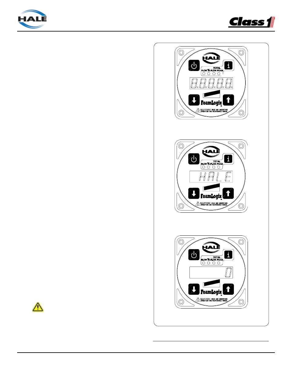
Watch the display on the control unit as the
apparatus electrical system is turned ON. Check
the control unit readout for:
❑
FLOW
❑
TOTAL FLOW
❑
% FOAM
❑
TOTAL FOAM
❑
all bar graph LEDs light
❑
“88888” appears for several seconds
❑
“HALE CLASS 1 2002” (or “HALE CLASS
1 [CURRENT DATE]”) scrolls across the
display
❑
The default display, zero (0), if no water is
flowing and FLOW LED
(See Figure 23: “Control Unit Ready Indication”)
If a default display does not appear, refer to Section
6: TROUBLESHOOTING for possible
WARM-UP/
SYSTEM CHECKING
causes and solutions.
INITIAL SYSTEM CHECK
After initial system power-up, low tank level sensor
operation, foam pump operation and flow sensor
calibration must be checked per the following:
CAUTION !
WATER IS USED AT THE SYSTEM INSTALLER
FACILITY TO VERIFY LOW TANK LEVEL SENSOR
SYSTEM READY
OPERATION AND FOAM PUMP
PERATION AS THE END USER SPECIFIED FOAM
CONCENTRATES MAY NOT BE READILY AVAILABLE.
FOAMLOGIX, Model 2.1A Class "A"
47
Electronic Foam Proportioning System
Installation
ISO 9001 CERTIFIED
SYSTEM INSTALLER START-UP
On initial power-up of the Hale FoamLogix
system, at the installer facility, the following
procedures must be followed.
INITIAL SYSTEM POWER CHECK
Watch the display on the control unit as the
apparatus electrical system is turned ON. Check
the control unit readout for:
❑
FLOW
❑
TOTAL FLOW
❑
% FOAM
❑
TOTAL FOAM
❑
all bar graph LEDs light
❑
“88888” appears for several seconds
❑
“HALE CLASS 1 2002” scrolls across the
display
❑
The default display, zero (0), if no water is
flowing and FLOW LED
(See Figure 23: “Control Unit Ready
Indication”).
If a default display does not appear, refer to
Section 6: TROUBLESHOOTING for possible
causes and solutions.
INITIAL SYSTEM CHECK
After initial system power-up, low tank level
sensor operation, foam pump operation and flow
sensor calibration must be checked per the
following:
CAUTION!
WATER IS USED AT THE SYSTEM INSTALLER
FACILITY TO VERIFY LOW TANK LEVEL SENSOR
OPERATION AND FOAM PUMP OPERATION AS
THE END USER SPECIFIED FOAM CONCEN-
TRATES MAY NOT BE READILY AVAILABLE.
Figure 23: Control Unit Ready Indication
SYSTEM READY
WARM-UP/SYSTEM CHECKING
INITIAL POWER-UP