Conversion (manual to dlc-xp/rc) – Pulsafeeder Pulsar DLC XP RC User Manual
Page 62
58
12. Conversion (Manual To DLC-XP/RC)
Your PULSAR can be easily converted from a Manual Stroke Adjustment Mechanism to the DLC-
XP/RC. The DLC-XP effectively replaces the Manual Cover Assembly. Use the following procedure for
conversion:
1. While running the pump motor, adjust the stroke
setting to approximately 50%.
2. Disconnect the power supply going to the PULSAR
drive motor.
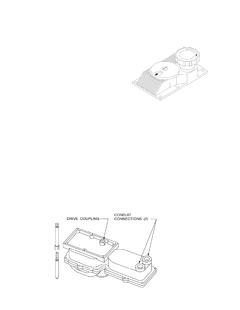
3. Remove the six Phillips Head screws that hold the
Manual Cover Assembly to the Eccentric Box (refer
to PMP-IOM-96 and the figure to the right).
Remove the Manual Cover vertically from the
Eccentric Box.
4. Note the position of the adjustment shaft 'flats' They
mate with a slot in the DLC-XP output shaft -- the only external moving part on the DLC-XP.
Familiarize yourself with these mating components prior to installation (refer to the figure below).
5. Locate the face on the bottom of the DLC-XP that mates with the face of the lip of the eccentric box.
The DLC-XP is oriented such that the conduit connections and access panel (with Serial Tag) reside
at the rear of the pump (as viewed from the reagent head) near the gear box.
6. Orient the DLC-XP properly at a comfortable height above the pump and align the slot in the DLC-
XP coupling with the 'flats' on the adjustment shaft. You may have to turn the adjustment shaft. If
necessary, turn it only in the counter clockwise direction.
7. Lower the DLC-XP onto the eccentric box. It may be necessary to tip the DLC-XP slightly towards
the motor to clear the motor adapter. With the DLC-XP approximately 25mm (1 inch) above the
eccentric box, make a fine adjustment to align the slot in the DLC-XP coupling with the adjustment
shaft 'flats.' Once aligned, lower the DLC-XP to mate with the eccentric box. Do not force it! When
the coupling is properly aligned, the DLC-XP will slide home under its own weight.
8. Install the 4 DLC-XP mounting screws and washers provided. Remove the 13 wiring access panel
screws.
9. Follow the instructions in section 5-Installation: Electrical Wiring of this manual for electrical
connections.
10. Perform the steps detailed in Section 6-Start Up Instructions.
11. Review Section 7-General Operation for detailed information on configuring your DLC-XP/RC and
its advanced features.