8 fuse replacement – Pulsafeeder Pulsar DLC XP RC User Manual
Page 20
16
5.8 Fuse
Replacement
Although Fuse replacement is not a part of normal installation, it is often likely that fuse failure will
result from improper wiring. The DLC-RC uses a total of 7 user replaceable fuses: 1 for the alarm relay
output, 2 for each of the Analog Input and Output Channels. Table 3 details fuse replacement
information:
Designator
Function
Rating
Manufacture P/N
Pulsafeeder P/N
F1 Alarm
Relay 1A@250VAC
WK4048-ND
NP5300026-000
F2-7
Analog Current I/O
50mA @ 250VAC
WK3022-ND
NP5300027-000
Table 3: Replacement Fuse Information
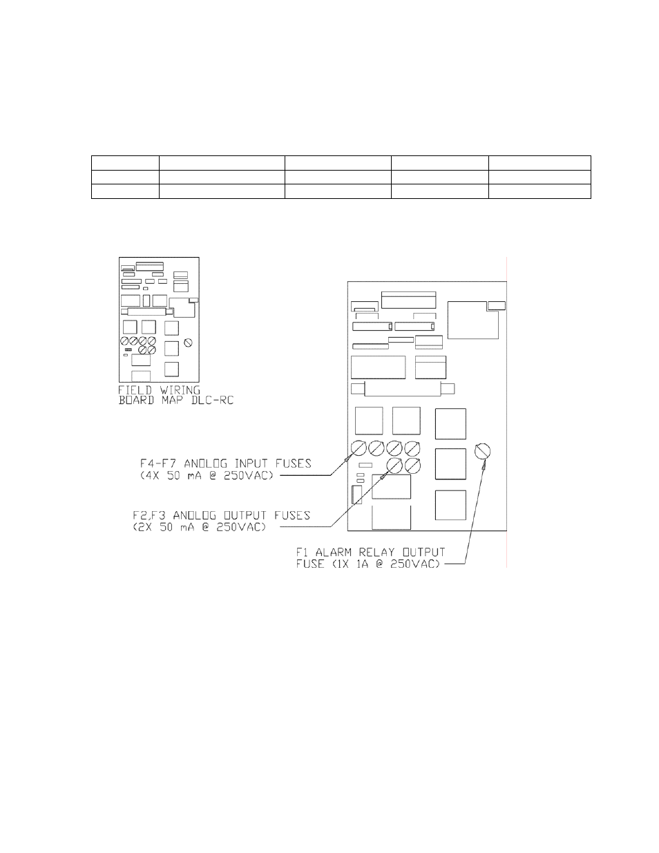
Figure 11 details the location of these fuses on the Field Wiring Board.
Figure 11. Fuse Location.
The Internal DLC-RC power supply is fused at 2Amps. This fuse is not user serviceable. The DLC-XP
power supply is not fuse protected. The user is responsible for supplying this element in an non-
hazardous location. The DLC-XP Stroke Length Adjustment Shaft Synchronous Motor is inherently
protected. It can operate continuously in a locked rotor state. The DLC-RC also monitors this motor's
duty cycle to maintain a 50% balance between ON and OFF times. The isolation elements of the
Current Inputs and Outputs, and the Motor Transistor Output are protected by self-resetting current limit
devices. These components are not user serviceable.