2 alarm and motor status outputs (dlc-rc) – Pulsafeeder Pulsar DLC XP RC User Manual
Page 19
15
5.7.2
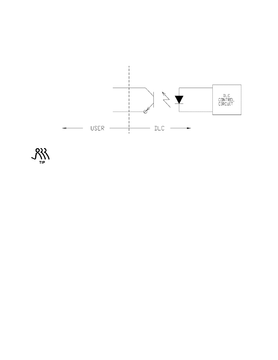
Alarm and Motor Status Outputs (DLC-RC)
The Alarm and Status outputs are solid state transistor type. Logic HIGH indicates an ON condition
while logic LOW indicates an OFF condition. They are commonly used to indicate an alarm status
and run status to external control equipment (i.e., PLC, PC or other digital controllers). These outputs
are limited to switching a maximum of 24 VDC. Refer to Figures 7 and 8.
Figure 8. Schematic, Transistor based Alarm Output.
VCC (+5VDC) and Ground are provided on terminals 7 and 8 of connector J5. A 250 ohm
resistor from terminal '7-VCC' to terminal '3-ALARM(+)' will cause a +5VDC signal to appear
between terminals '4-ALARM(-)' and 8-DCGND' when the alarm output is activated. This
technique is only recommended if the input on the external device is isolated from all other
inputs, outputs and grounds.
An opto-coupler is used to achieve total isolation of this device. As such, the external control
equipment must generate the supply on the positive output and detect the return of that signal when
the output is activated by the DLC. In a typical application, attach the terminal labeled '3-
ALARM(+)' -- the collector terminal -- to the external equipment's logic supply (refer to Figure 8).
Connect the terminal labeled '4-ALARM(-)' -- the emitter terminal -- to the positive input of the
equipment. The negative input of the equipment should be connected to its isolated ground. A series
resistance of 400 ohms is recommended especially when a sinking current (e.g., a photo-diode of an
opto-isolator). The Alarm output cannot be directly configured in software. It follows the Alarm
Relay output. Similarly, the status output is available at terminals 5 (+) and 6 (-) and it’s status will
follow the operation of the pump motor.