Pulsafeeder MPC Vector User Manual
Page 16
10
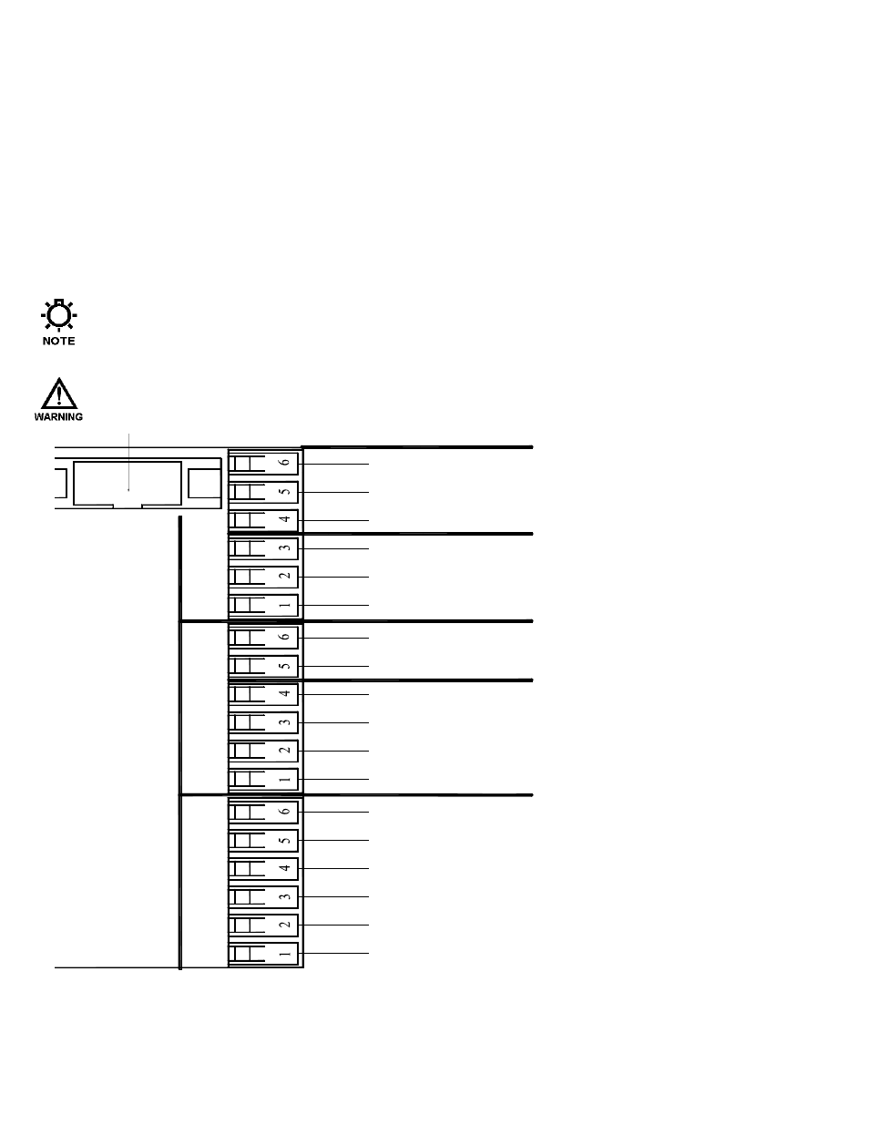
5.3.4 Input/Output Signal Wiring
Signal wiring is routed through the two unused conduit openings at the base of the MPC VECTOR.
All input/output signals are connected to the terminal strips at the edge of the MPC VECTOR circuit
board except for flow meter feedback which is connected to a separate terminal block. Use caution
to observe proper wire location and signal polarity. Always cap or plug unused openings. Wires
should be routed with in the enclosure in a manner that maintains separation between high voltage
and low voltage conductors. Ensure all low voltage wiring is installed as per any applicable local
and national electrical codes and regulations.
Utilize 16 to 22 AWG, 250 V shielded cable with a 75
o
C insulation rating (or better) for all signal
input and output wiring. Recommended strip length is 0.39” or 10 mm. Refer to Figure 4 below for
signal connection locations.
Unused conduit openings should be plugged as required to avoid ingress of moisture and contaminants
into the MPC VECTOR enclosure. Do not remove the factory provided plug from openings that are not
required for field wiring.
I
T IS RECOMMENDED THAT A WRIST STRAP BE WORN WHEN MAKING CONNECTIONS TO ANY PRINTED
CIRCUIT BOARD
.
BLACK/WHITE
WHITE
SHIELD
BLACK/GREEN -GREEN
BLACK/RED
RED
J20
DIGITAL OUT 3
DIGITAL OUT 2
GROUND
ANALOG OUT 1
GROUND
DIGITAL OUT 1
ANALOG IN 2
ANALOG IN 1
GROUND
GROUND
DIGITAL IN 2
DIGITAL IN 1
J11
J14
J23
4-20 INPUT
DIGITAL INPUT
REMOTE
4-20 OUTPUT
DIGITAL OUTPUT
Figure 4a – Signal Connections
(
P R O C E S S S I G N A L
)
(
F L O W M E T E R S I G N A L
)