3 power wiring diagram – Pulsafeeder MPC Vector User Manual
Page 15
9
secure the conductor, making certain that the terminal grips the wire, not the insulation. Ensure that
all wiring meets applicable local and national codes and requirements.
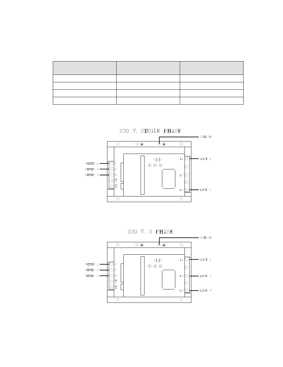
5.3.3 Power Wiring Diagram
MPC VECTOR Drive
Terminal
Single Phase 208/230 VAC Three Phase 208/230 VAC
L1
Line 1
Line 1
L2
N/C
Line 2
L3
Line 2
Line 3
Ground Plate
Ground
Ground
Table 2 – AC Drive Terminals
Figure 3 – AC Power Connections
Wait a minimum of 5 minutes after disconnecting power before servicing the MPC VECTOR or pump motor.
Capacitors retain a charge even after power is removed from the controller.
See also other documents in the category Pulsafeeder Pumps:
- Pulsa GLM DM1-6 (30 pages)
- Pulsa GLM DM7 (33 pages)
- Pulsa 340 (24 pages)
- Pulsa Series 200-680C (20 pages)
- Pulsa Series 680 EN (26 pages)
- Pulsar 25H (54 pages)
- Pulsar Shadow (48 pages)
- PulsaPro 900 EN (71 pages)
- Polyfeeder EN (47 pages)
- PULSAlarm (24 pages)
- Eclipse Hypopump (140 pages)
- ECO Series Back Pressure Valve Instructions (1 page)
- ECO Series Relief Valve Instructions (1 page)
- Isochem RGT IOM (44 pages)
- Pulsar Series HypoPump (15 pages)
- Pulsar Series HypoPump2 (27 pages)
- MPC (56 pages)
- Pulsa Series Pulsamatic Controls (34 pages)
- Pulsar DLC (120 pages)
- Pulsar DLC XP RC (68 pages)
- Pulsar DLCM (135 pages)
- Pulsar ECA NEMA4X (38 pages)
- Pulsar ECA NEMA7 (23 pages)
- Chem-Tech Series XPV EN (19 pages)
- Chem-Tech Series XP EN (22 pages)
- Chem-Tech Series XP TIMER EN (20 pages)
- Chem-Tech Series Prime Performance EN (12 pages)
- Chem-Tech Series Prime Performance EN (3 pages)
- MEC-O-MATIC VSP Series (8 pages)
- OMNI Series DC7 (34 pages)
- OMNI Series DC2-6 EN (46 pages)
- PULSAtron Series A Plus EN (16 pages)
- PULSAtron Series ET (17 pages)
- PULSAtron Series MP EN (32 pages)
- PULSAtron Series T7 (23 pages)
- Digital Glycol Feeder DGF1 (45 pages)
- Polymer Makedown Automatic Systems EN (15 pages)
- Polymer Makedown Systems EN (11 pages)
- Pre-Engineered Skid Systems (23 pages)