2 power wiring information – Pulsafeeder MPC Vector User Manual
Page 14
8
5.3.2 Power Wiring Information
• Verify the correct supply voltage (230VAC single-phase or three-phase) with the nameplate
affixed to your MPC VECTOR. Ensure that your supply voltage matches the MPC VECTOR
configuration.
• The 1 hp, 2 hp, and 3 hp AC drives use single phase or three phase 230VAC input. The 5 hp
AC drive must be powered by three phase 230VAC input only.
• Wires should be routed within the enclosure in a manner that maintains separation between
high voltage and low voltage conductors. High voltage conductors should be routed to the side
opposite the control circuitry.
• Incoming power wiring should adhere to all applicable local and national electrical codes and
regulations. A circuit breaker or fuse must be provided as noted below.
• Upon initial application of AC power, a current inrush will occur to charge the DC bus
capacitors. This is normal operation, and breakers and other circuit protection devices should
be sized accordingly.
The MPC VECTOR requires one connection to an external power source. It uses this same
connection to power its own supply as well as the AC pump motor. You must take all of these loads
into consideration when sizing the branch circuit (see Table 1). A circuit breaker or disconnect
switch with fuses must be wired in series with terminals L1 and L2/N in accordance with all
applicable local and national electrical codes and regulations. The circuit breaker or disconnect
switch shall be located in close proximity to the MPC VECTOR controller installation, and must be
marked or labeled to identify it as the power disconnect for the MPC VECTOR.
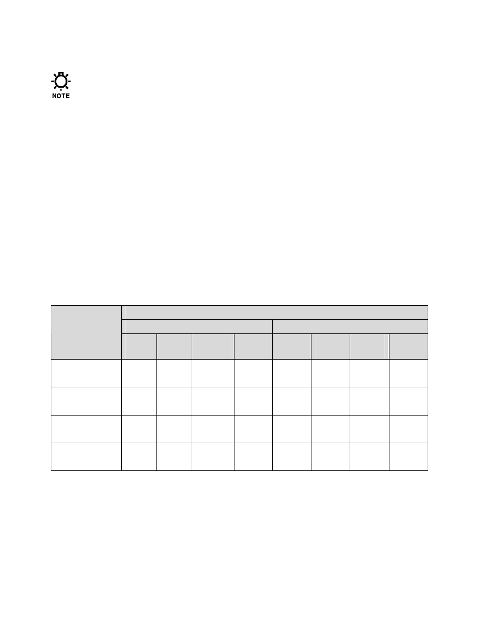
Recommended Minimum Wiring and Circuit Breaker
Single Phase 208/230 VAC
Three Phase 208/230 VAC
Power
Requirements
Actual
Draw
Circuit
Breaker
Wire
Size
Wire
Size
Actual
Draw
Circuit
Breaker
Wire
Size
Wire
Size
MPC VECTOR
and 1.0 Hp motor
10.6 A
15 A
14 AWG
2.0 mm
2
5.8 A
10 A
14 AWG
2.0 mm
2
MPC VECTOR
and 2.0 Hp motor
14.8 A
20 A
14 AWG
2.0 mm
2
9.1 A
15 A
14 AWG
2.0 mm
2
MPC VECTOR
and 3.0 Hp motor
19.7 A
25 A
12 AWG
3.5 mm
2
12.4 A
20 A
14 AWG
2.0 mm
2
MPC VECTOR
and 5.0 Hp motor
---
---
---
---
19.6 A
25 A
12 AWG
3.5 mm
2
Table 1 – Sizing Branch Circuits
The MPC VECTOR controller is provided with a 7/8” thru hole for incoming AC power wiring and
a 7/8” thru hole for motor wiring at the bottom of the enclosure. Utilize the appropriate conduit
fittings to route and seal the supply wires into the MPC VECTOR enclosure.
The power wires are secured to the terminal strip at the bottom end of the AC drive as per Table 2.
Remove approximately 0.20 – 0.25” of insulation from the end of each conductor. Loosen the
terminal strip screw, and insert the stripped wire end fully into the terminal. Tighten the screw to