Figure53 typical configuration – Allied Telesis AT-S20 User Manual
Page 68
Virtual LAN Configuration
5-4
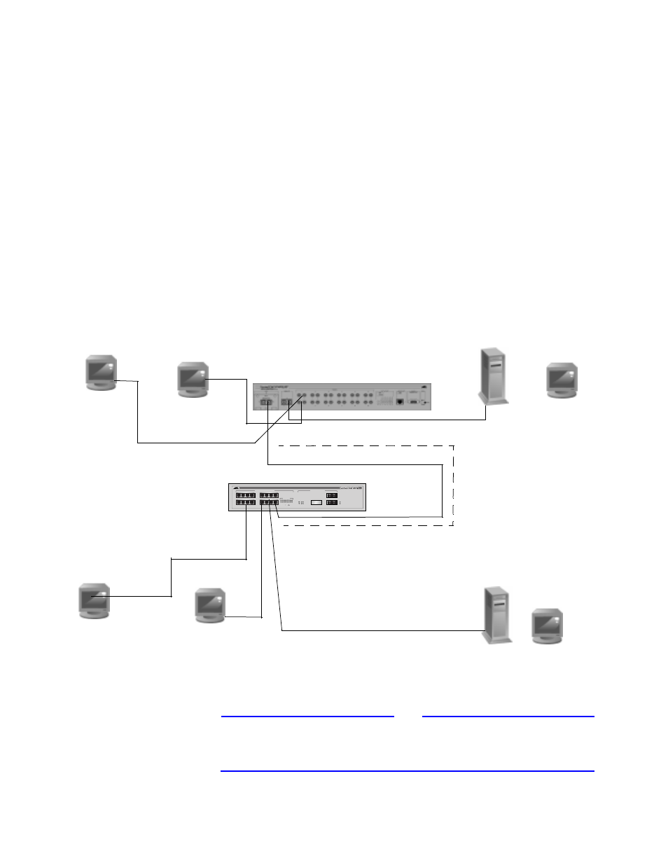
The AT-8518 is configured as follows:
❑
The AT-8518 will have a VLAN named “Default VLAN”. Ports 1
and 3 will be both tagged and a port-based member of
“Default VLAN” with a PVID and a VLAN ID of 1. Port 10 is
added as a tag member so that “Default VLAN” will have
access to the uplink between switches.
❑
The AT-8518 will have a VLAN named “VLAN 2”. Port 2 will be
tagged and a port-based member of VLAN #2 with a PVID and
VLAN ID of 2. Port 10 is added as a tag member so that “VLAN
2” will have access to the uplink between switches.
❑
The AT-8518 will have a VLAN named “Uplink”. Port 10 will be
tagged and a port-based member of VLAN “Uplink” with a
PVID and a VLAN ID of 3. See Figure 5-3.
Figure 5-3 Typical Configuration
Note
The PVIDs must match on the trunk or uplink port between the
AT-8518 switch and the AT-3714FXL switch. For example, they both
must have IDs of 1.
AT-3714FXL
10 / 100BASE-T ETHERNET SWITCH
WITH GIGABIT ETHERNET
1000BASE-X NETWORK PORTS
10/100BASE-TX MDI-X NETWORK PORTS
POWER
DIAG
ACTIVITY
LINK
1
2
3
4
9
10
11
12
5
6
7
8
13
14
15
16
1
2
3
4
5
6
7
8
9
10
11
12
13
14
15
16
LINK /ACTIVITY
LINK
ACTIVITY
DISABLED
17R
17
18
18
17R
17
AT-8518 Switch
Default VLAN
Legacy Sever B
802.1Q Compliant Server “A”
Workstation #1
Workstation #2
VLAN #2
Port 1
Default VLAN
Workstation #3
Port 2
Port 10
Port 15
PVID = 3
PVID = 3
Port 14
Port 1
Port 2
Port 3
Default VLAN
Workstation #4
VLAN 2
VLAN #2
“Uplink” VLAN