Configuring multiple spanning tree, Defining mstp properties, E configuring multiple spanning tree – Allied Telesis AT-S94 User Manual
Page 143
Configuring Spanning Tree
Configuring Multiple Spanning Tree
Page 143
Configuring Multiple Spanning Tree
Multiple Spanning Tree Protocol (MSTP) provides differing load balancing scenarios. For example, while port A is
blocked in one STP instance, the same port can be placed in the Forwarding state in another STP instance.
This section contains the following topics:
•
•
•
Defining MSTP Instance Mappings
•
Defining MSTP Instance Settings
Defining MSTP Properties
The MSTP Page contains information for defining global MSTP settings, including region names, MSTP revisions,
and maximum hops.
To define MSTP:
1.
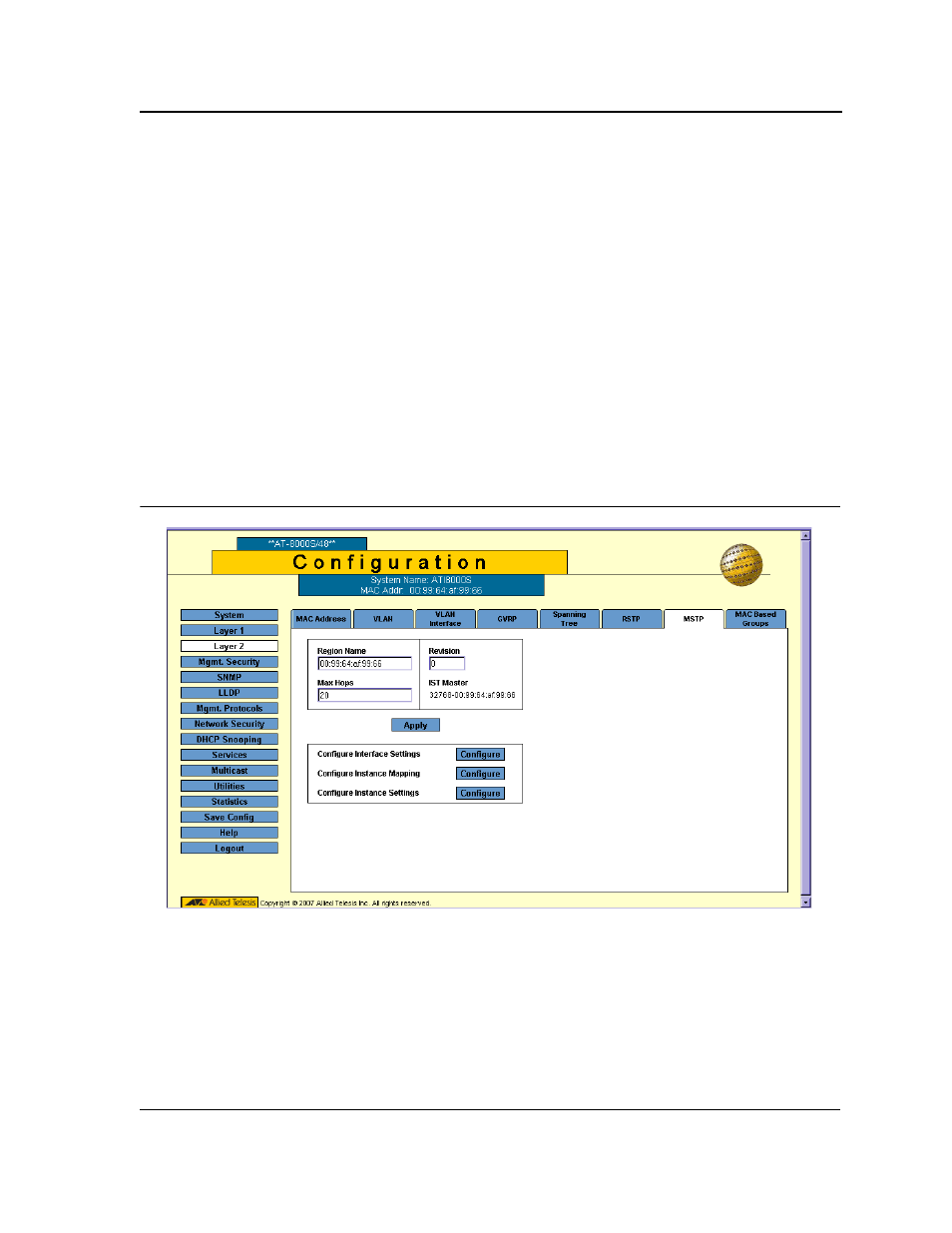
Click Layer 2 > MSTP. The MSTP Page opens:
Figure 94: MSTP Page
The MSTP Page contains the following fields:
•
Region Name — User-defined STP region name.
•
Revision — An unsigned 16-bit number that identifies the revision of the current MSTP configuration. The
revision number is required as part of the MSTP configuration. The possible field range is 0-65535.
•
Max Hops — Specifies the total number of hops that occur in a specific region before the BPDU is discarded.
Once the BPDU is discarded, the port information is aged out. The possible field range is 1-40. The field
default is 20 hops.