Figure 58. connecting the ac power cord – Allied Telesis x610 Series Layer 3 User Manual
Page 99
x610 Series Layer 3 Gigabit Ethernet Switches Installation Guide
99
Powering on a Switch with an AC Power Supply Module
To power on a switch with an AC Power Supply Module, perform the
following procedure:
1. Position the power cord retaining clip in the up position, as shown in
Figure 57. Note that the AT-PWR1200 power supply does not have a
retaining clip.
Figure 57. Power Cord Retaining Clip in the Up Position
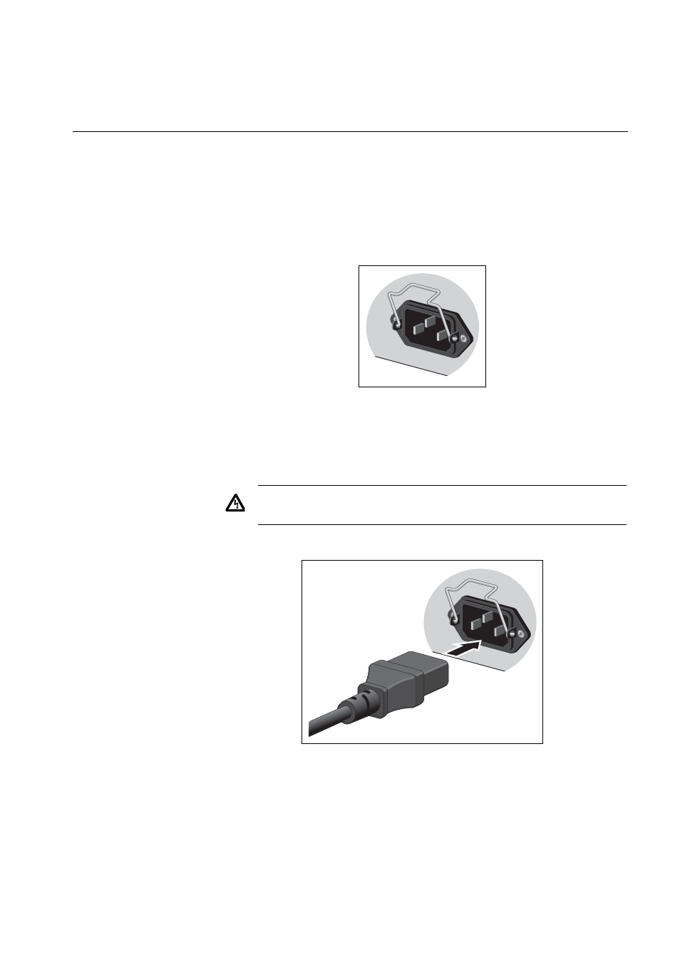
2. Plug the power cord into the AC power connector on the rear panel of
the unit, as shown in Figure 58. Lower the power cord retaining clip to
secure the power cord to the unit.
Figure 58. Connecting the AC Power Cord
3. Connect the other end of the power cord to an appropriate AC power
outlet. For power specifications for the switch, refer to “Power
Warning:
Power cord is used as a disconnection device. To de-
energize equipment, disconnect the power cord.
E3
100-240V
AC
~
100-240V
AC
~
- AT-GS908M (54 pages)
- AT-x230-10GP (80 pages)
- AT-GS950/48PS (64 pages)
- AT-GS950/10PS (386 pages)
- AT-GS950/16PS (386 pages)
- AT-GS950/48PS (386 pages)
- AT-9000 Series (258 pages)
- AT-9000 Series (1480 pages)
- IE200 Series (70 pages)
- AT-GS950/48 (60 pages)
- AT-GS950/48 (410 pages)
- AT-GS950/8 (52 pages)
- AT-GS950/48 (378 pages)
- SwitchBlade x8106 (322 pages)
- SwitchBlade x8112 (322 pages)
- SwitchBlade x8106 (240 pages)
- SwitchBlade x8112 (240 pages)
- AT-TQ Series (172 pages)
- AlliedWare Plus Operating System Version 5.4.4C (x310-26FT,x310-26FP,x310-50FT,x310-50FP) (2220 pages)
- FS970M Series (106 pages)
- 8100L Series (116 pages)
- 8100S Series (140 pages)
- x310 Series (116 pages)
- x310 Series (120 pages)
- AT-GS950/24 (404 pages)
- AT-GS950/24 (366 pages)
- AT-GS950/16 (44 pages)
- AT-GS950/16 (404 pages)
- AT-GS950/16 (364 pages)
- AT-GS950/8 (364 pages)
- AT-GS950/8 (52 pages)
- AT-GS950/8 (404 pages)
- AT-8100 Series (330 pages)
- AT-8100 Series (1962 pages)
- AT-FS970M Series (330 pages)
- AT-FS970M Series (1938 pages)
- SwitchBlade x3112 (294 pages)
- SwitchBlade x3106 (288 pages)
- SwitchBlade x3106 (260 pages)
- SwitchBlade x3112 (222 pages)
- AT-S95 CLI (AT-8000GS Series) (397 pages)
- AT-S94 CLI (AT-8000S Series) (402 pages)
- AT-IMC1000T/SFP (23 pages)
- AT-IMC1000TP/SFP (24 pages)
- AT-SBx3106WMB (44 pages)