Resiliency link, Ring configuration, Chapter 2: virtual chassis stacking 60 – Allied Telesis x610 Series Layer 3 User Manual
Page 60
Chapter 2: Virtual Chassis Stacking
60
Ring Configuration
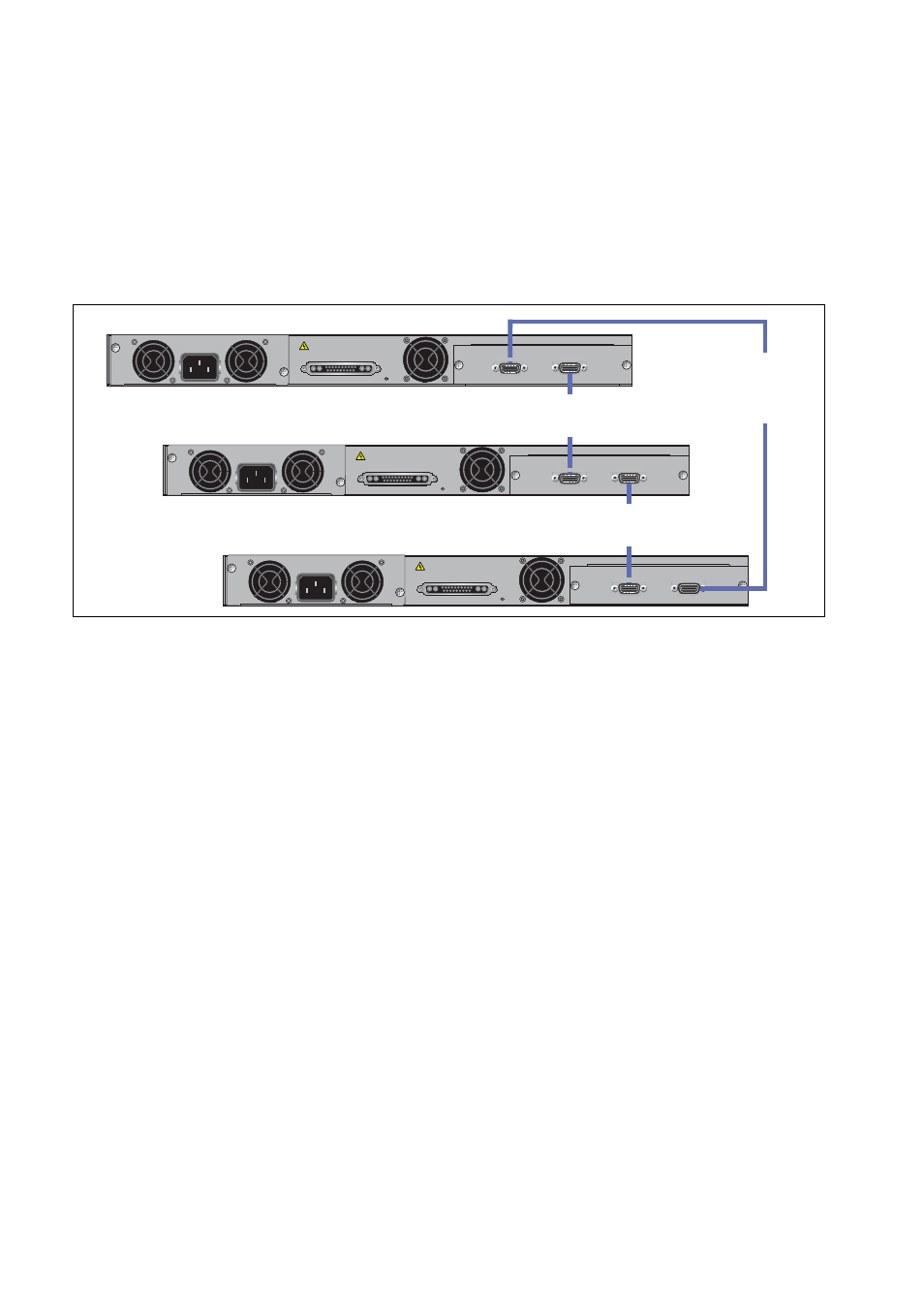
A virtual stack using x610 switches can comprise up to 8 stack members
connected in a ring topology. Figure 30 shows a ring comprising 3 stacked
x610 series switches with AT-StackXG stacking modules installed.
Because an alternate path is provided between the stack members, this
topology offers a very resilient configuration.
Figure 30. VCStack Ring Topology Using x610 Switches
Resiliency Link
The purpose of the resiliency link is to provide the stack members with
status information that enables them to detect whether the stack master is
still operational after it has suffered either a power-down or software
lock-up. This enables the other stack members to always re-elect a new
stack master safely, and to avoid a situation where there are two isolated
masters both running the same configuration
A resiliency link operates using a designated VLAN running over switch
port connections between each stack member.
For more information about the stack resiliency link refer to the Stacking
Introduction
and Stacking Commands chapters in the AlliedWare Plus
Operating System Software Reference
from www.alliedtelesis.com.
PO
WER SUPPL
Y
RPS
READY
RPS INPUT
12V/21A MAX
STACKING
WARNING
This unit may have more than one power input. To reduce the risk of
electric shock, disconnect both A/C and RPS inputs before servicing
unit.
100-240VAC~
High Speed Stacking Cables
Model Number AT-StackXG/0.5
(0.5 meters) as supplied or
Model Number AT-StackXG/1
(1.0 meter)
PO
WER SUPPL
Y
RPS
READY
RPS INPUT
12V/21A MAX
STACKING
WARNING
This unit may have more than one power input. To reduce the risk of
electric shock, disconnect both A/C and RPS inputs before servicing
unit.
100-240VAC~
AT-StackXG
STACK PORT 2
PO
WER SUPPL
Y
RPS
READY
RPS INPUT
12V/21A MAX
STACKING
WARNING
This unit may have more than one power input. To reduce the risk of
electric shock, disconnect both A/C and RPS inputs before servicing
unit.
100-240VAC~
AT-StackXG
STACK PORT 2
AT-StackXG
STACK PORT 1
STACK PORT 1
High Speed Stacking Cables
Model Number AT-StackXG/0.5
(0.5 metres)
STACK PORT 1
High Speed Stacking Cables
Model Number AT-StackXG/0.5
(0.5 metres)
STACK PORT 2