Figure 34. power cord retaining clip, Table 16. stack led descriptions – Allied Telesis x610 Series Layer 3 User Manual
Page 64
Chapter 2: Virtual Chassis Stacking
64
Stack Member Identification
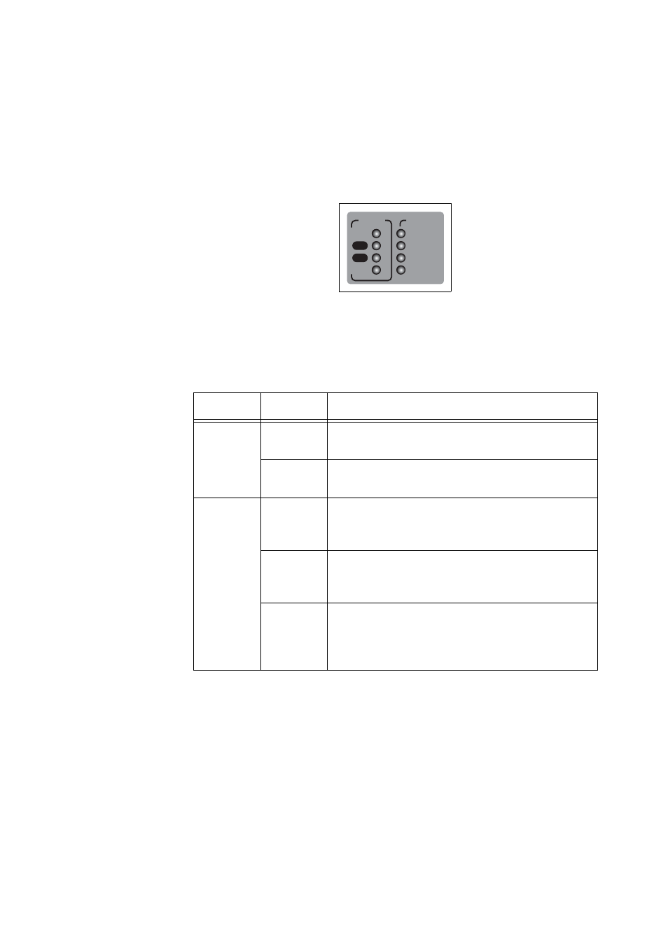
When a switch becomes a member of a VCStack it is assigned a Stack
Member-ID. Stack status information is displayed on the STACK and
STATUS LEDs on the switch’s front panel, shown in Figure 33.
Figure 33. STACK and STATUS LEDs
The LEDs that indicate the switch’s status within the stack are shown in
Table 16. STACK LED Descriptions
LED
State
Description
MSTR
Off
The switch is not part of a stack or is a member
unit of the stack.
Solid
Green
The switch is the master unit of the stack.
L/A 1
Off
Stack Port 1 has not established a link to a
stacking port on another VCStack stacking
module.
Solid
Green
Stack Port 1 has established a link to a
stacking port on another VCStack stacking
module.
Flashing
Green
Stack Port 1 has established a link to a
stacking port on another VCStack stacking
module and is sending or receiving packet
traffic.
STATUS
FAULT
MASTER
RPS
PWR
PRES
MSTR
L/A
L/A
1
2
STACK
- AT-GS908M (54 pages)
- AT-x230-10GP (80 pages)
- AT-GS950/48PS (64 pages)
- AT-GS950/10PS (386 pages)
- AT-GS950/16PS (386 pages)
- AT-GS950/48PS (386 pages)
- AT-9000 Series (258 pages)
- AT-9000 Series (1480 pages)
- IE200 Series (70 pages)
- AT-GS950/8 (52 pages)
- AT-GS950/48 (378 pages)
- AT-GS950/48 (60 pages)
- AT-GS950/48 (410 pages)
- SwitchBlade x8106 (322 pages)
- SwitchBlade x8112 (322 pages)
- SwitchBlade x8106 (240 pages)
- SwitchBlade x8112 (240 pages)
- AT-TQ Series (172 pages)
- AlliedWare Plus Operating System Version 5.4.4C (x310-26FT,x310-26FP,x310-50FT,x310-50FP) (2220 pages)
- FS970M Series (106 pages)
- 8100S Series (140 pages)
- 8100L Series (116 pages)
- x310 Series (116 pages)
- x310 Series (120 pages)
- AT-GS950/24 (366 pages)
- AT-GS950/16 (44 pages)
- AT-GS950/24 (404 pages)
- AT-GS950/16 (404 pages)
- AT-GS950/16 (364 pages)
- AT-GS950/8 (404 pages)
- AT-GS950/8 (364 pages)
- AT-GS950/8 (52 pages)
- AT-8100 Series (330 pages)
- AT-8100 Series (1962 pages)
- AT-FS970M Series (1938 pages)
- AT-FS970M Series (330 pages)
- SwitchBlade x3106 (288 pages)
- SwitchBlade x3112 (294 pages)
- SwitchBlade x3106 (260 pages)
- SwitchBlade x3112 (222 pages)
- AT-S95 CLI (AT-8000GS Series) (397 pages)
- AT-S94 CLI (AT-8000S Series) (402 pages)
- AT-IMC1000T/SFP (23 pages)
- AT-IMC1000TP/SFP (24 pages)
- AT-SBx3106WMB (44 pages)