Resiliency link configurations via switch ports, Figure 33. stack and status leds – Allied Telesis x610 Series Layer 3 User Manual
Page 61
x610 Series Layer 3 Gigabit Ethernet Switches Installation Guide
61
Resiliency Link
Configurations
via Switch Ports
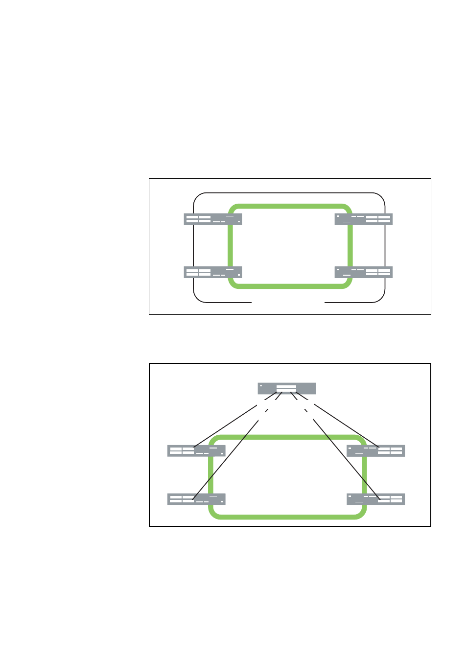
Two resiliency-link configurations that connect to switch ports are shown
below. Figure 31 shows the resiliency link connecting in a ring topology,
whilst Figure 32 shows the resiliency link connecting to its switch ports via
a network hub. In both configurations, the resiliency link connections are
made using the ResiliencyLink VLAN and attaching the switch ports to the
VLAN.
For more information about the stack resiliency link refer to the Stacking
Introduction
and Stacking Commands chapters in the AlliedWare Plus
Operating System Software Reference
from www.alliedtelesis.com.
Figure 31. Resiliency link Connecting to Switch Ports Over the
ResiliencyLink VLAN
Figure 32. Resiliency link Connecting to sWitch Ports Over the
ResiliencyLink VLAN Using a Network Hub
x610-24Ts
x610-24Ts
x610-24Ts
x610-24Ts
Stacking Links
Connecting to Switch Ports
Stack Resiliency Link -
ResiliencyLink VLAN
x610-24Ts
x610-24Ts
x610-24Ts
Network Hub
x610-24Ts
Stacking Links
Resiliency Links
to Switch Ports