System status leds, Figure 18. system status leds on the front panel, Figure 19. system status led on the rear panel – Allied Telesis x610 Series Layer 3 User Manual
Page 41: Table 9. system status led descriptions
x610 Series Layer 3 Gigabit Ethernet Switches Installation Guide
41
System STATUS LEDs
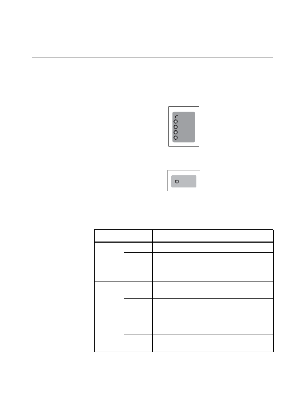
The system STATUS LEDs on the front panel display general status
information. To locate these LEDs, see Figure 18. On the rear panel there
is a single system STATUS LED, as shown in Figure 19. See Table 9 for a
description of the system STATUS LEDs.
Figure 18. System STATUS LEDs on the Front Panel
Figure 19. System STATUS LED on the Rear Panel
Table 9. System STATUS LED Descriptions
LED
State
Description
FAULT
Off
Indicates normal operation.
Solid
Red
Indicates a fault. The switch or the operating
system software has malfunctioned. (Refer to
Chapter 5, “Troubleshooting” on page 103 for
instructions on how to troubleshoot a problem.)
MASTER Off
Indicates that the switch is not the Stack
Master.
Flashing
Green
Indicates the specific stack member’s ID of the
switch in response to the ‘show stack indicator’
command. The LED will repeatedly flash ‘n’
times in quick succession, followed by a longer
pause, where n is the stack member's ID.
Solid
Green
Indicates that the switch is the Stack Master.
STATUS
FAULT
MASTER
RPS
PWR
RPS
READY