Table 7. sfp+ slot led descriptions, Figure 16, and figure 17, Figure 17 – Allied Telesis x610 Series Layer 3 User Manual
Page 39: N in table 7 and
x610 Series Layer 3 Gigabit Ethernet Switches Installation Guide
39
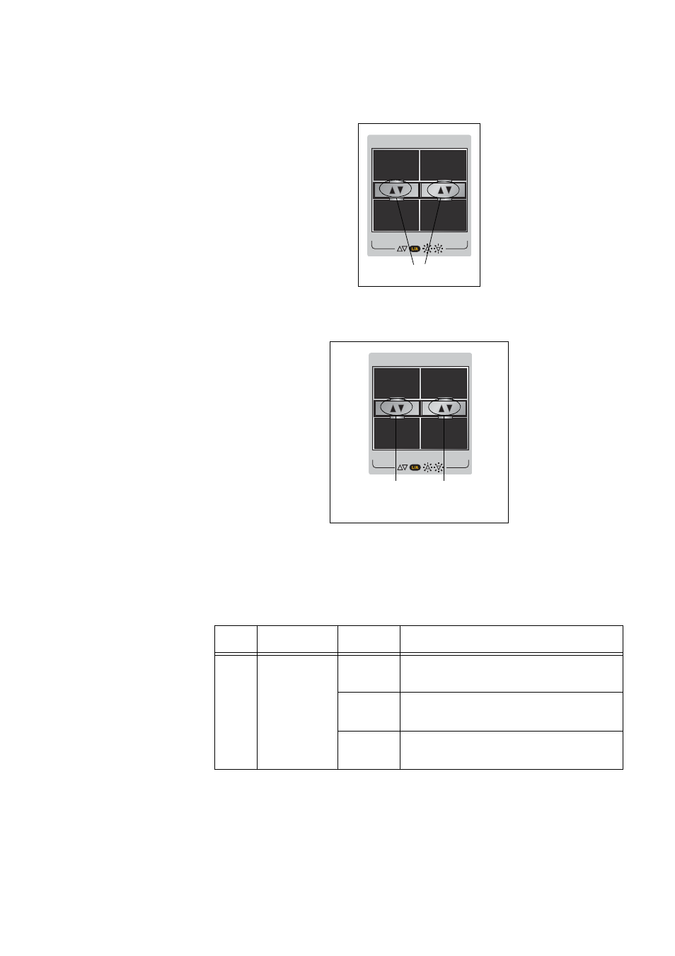
Figure 16. SFP LEDs on x610-48Ts and x610-48Ts-POE+ Switches
Figure 17. SFP and SFP+ LEDs on x610-48Ts/X and x610-48Ts/X-POE+
Switches
Table 7. SFP+ Slot LED Descriptions
LED
Function
State
Description
L/A
Link Status
and Activity
Off
No link has been established between
the port and the end node.
Solid
Green
The port has established a link at
10 Gbps.
Flashing
Green
Packets are being received or
transmitted at 10 Gbps.
SFP
47
45
46
48
1000
/
100
S
FP LINK/ACT LED
s
SFP
49
SFP+
47
10G
1000
/
100
48
50
S
FP LINK/ACT
LED
s
S
FP+ LINK/ACT
LED
s
See also other documents in the category Allied Telesis Computer hardware:
- AT-GS908M (54 pages)
- AT-x230-10GP (80 pages)
- AT-GS950/48PS (64 pages)
- AT-GS950/10PS (386 pages)
- AT-GS950/16PS (386 pages)
- AT-GS950/48PS (386 pages)
- AT-9000 Series (258 pages)
- AT-9000 Series (1480 pages)
- IE200 Series (70 pages)
- AT-GS950/48 (60 pages)
- AT-GS950/48 (410 pages)
- AT-GS950/8 (52 pages)
- AT-GS950/48 (378 pages)
- SwitchBlade x8106 (322 pages)
- SwitchBlade x8112 (322 pages)
- SwitchBlade x8106 (240 pages)
- SwitchBlade x8112 (240 pages)
- AT-TQ Series (172 pages)
- AlliedWare Plus Operating System Version 5.4.4C (x310-26FT,x310-26FP,x310-50FT,x310-50FP) (2220 pages)
- FS970M Series (106 pages)
- 8100L Series (116 pages)
- 8100S Series (140 pages)
- x310 Series (116 pages)
- x310 Series (120 pages)
- AT-GS950/24 (404 pages)
- AT-GS950/24 (366 pages)
- AT-GS950/16 (44 pages)
- AT-GS950/16 (404 pages)
- AT-GS950/16 (364 pages)
- AT-GS950/8 (52 pages)
- AT-GS950/8 (404 pages)
- AT-GS950/8 (364 pages)
- AT-8100 Series (330 pages)
- AT-8100 Series (1962 pages)
- AT-FS970M Series (330 pages)
- AT-FS970M Series (1938 pages)
- SwitchBlade x3112 (294 pages)
- SwitchBlade x3106 (288 pages)
- SwitchBlade x3106 (260 pages)
- SwitchBlade x3112 (222 pages)
- AT-S95 CLI (AT-8000GS Series) (397 pages)
- AT-S94 CLI (AT-8000S Series) (402 pages)
- AT-IMC1000T/SFP (23 pages)
- AT-IMC1000TP/SFP (24 pages)
- AT-SBx3106WMB (44 pages)