Installing the power cord retaining clip, Figure 36. removing the feet – Allied Telesis x610 Series Layer 3 User Manual
Page 76
Chapter 3: Installing the Hardware
76
Installing the Power Cord Retaining Clip
This section applies to the fixed power supplies installed in the x610-24Ts,
x610-24Ts/X, x610-48Ts, and x610-48Ts/X switches and to the
AT-PWR250 and AT-PWR800 power supplies.
Perform the following procedure to install the power cord retaining clip on
the switches:
1. Locate the power cord retaining clip, shown in Figure 34.
Figure 34. Power Cord Retaining Clip
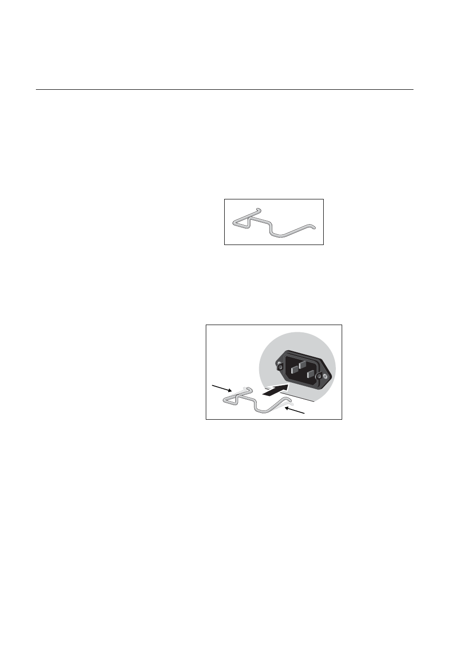
2. Install the clip on the AC power connector on the rear panel of the
switch. With the ‘u’ of the clip facing down, press the sides of the clip
toward the center and insert the short ends into the holes in the
retaining bracket, as shown in Figure 35.
Figure 35. Inserting the Retaining Clip into the Retaining Bracket
You are now ready to install the switches in the equipment rack, as
explained in the next procedure.
100-240V
AC
~
- AT-GS908M (54 pages)
- AT-x230-10GP (80 pages)
- AT-GS950/48PS (64 pages)
- AT-GS950/10PS (386 pages)
- AT-GS950/16PS (386 pages)
- AT-GS950/48PS (386 pages)
- AT-9000 Series (258 pages)
- AT-9000 Series (1480 pages)
- IE200 Series (70 pages)
- AT-GS950/48 (60 pages)
- AT-GS950/48 (410 pages)
- AT-GS950/8 (52 pages)
- AT-GS950/48 (378 pages)
- SwitchBlade x8106 (322 pages)
- SwitchBlade x8112 (322 pages)
- SwitchBlade x8106 (240 pages)
- SwitchBlade x8112 (240 pages)
- AT-TQ Series (172 pages)
- AlliedWare Plus Operating System Version 5.4.4C (x310-26FT,x310-26FP,x310-50FT,x310-50FP) (2220 pages)
- FS970M Series (106 pages)
- 8100L Series (116 pages)
- 8100S Series (140 pages)
- x310 Series (116 pages)
- x310 Series (120 pages)
- AT-GS950/24 (404 pages)
- AT-GS950/24 (366 pages)
- AT-GS950/16 (44 pages)
- AT-GS950/16 (404 pages)
- AT-GS950/16 (364 pages)
- AT-GS950/8 (364 pages)
- AT-GS950/8 (52 pages)
- AT-GS950/8 (404 pages)
- AT-8100 Series (330 pages)
- AT-8100 Series (1962 pages)
- AT-FS970M Series (330 pages)
- AT-FS970M Series (1938 pages)
- SwitchBlade x3112 (294 pages)
- SwitchBlade x3106 (288 pages)
- SwitchBlade x3106 (260 pages)
- SwitchBlade x3112 (222 pages)
- AT-S95 CLI (AT-8000GS Series) (397 pages)
- AT-S94 CLI (AT-8000S Series) (402 pages)
- AT-IMC1000T/SFP (23 pages)
- AT-IMC1000TP/SFP (24 pages)
- AT-SBx3106WMB (44 pages)