Choosing a method for attaching the power wires – Allied Telesis AT-SBx31CFC960 User Manual
Page 187
SwitchBlade x3112 Chassis Switch and AT-SBx31CFC960 Card Installation Guide
187
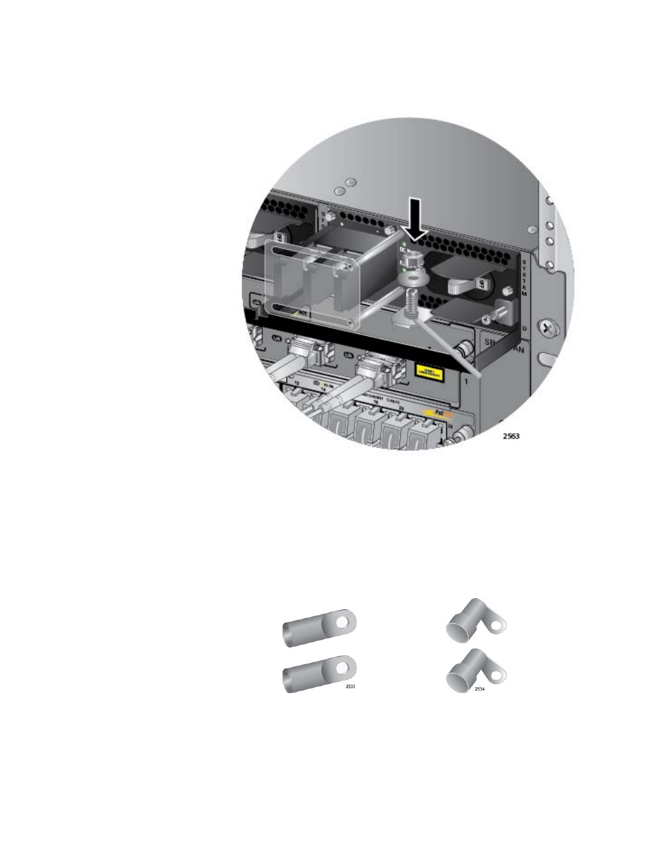
4. Secure the wire with the nut and washer removed in step 2, and an 8
mm wrench, as shown in Figure 125.
Figure 125. Securing the Bare Grounding Wire to the Grounding Post
Choosing a
Method for
Attaching the
Power Wires
The AT-SBxPWRSYS1 DC Power Supply comes with two sets of power
wire terminals. The terminals are shown in Figure 126. You may use either
set to connect the positive (+) and negative (-) wires to the terminal block
on the power supply. The straight terminals are used to route the wires
above or below the terminal block. The right angle terminals are used to
route the power wires directly away from the terminal block.
Figure 126. Power Wire Terminals
Straight Terminals
Right Angle Terminals