Allied Telesis AT-SBx31CFC960 User Manual
Page 130
Chapter 7: Installing the AT-SBx31CFC960 Card and Ethernet Line Cards
130
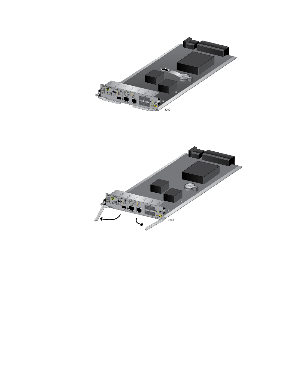
Figure 70. Removing the Battery Insulator
5. Move the locking handles on the front panel to the open position, as
shown in Figure 71.
Figure 71. Opening the Locking Handles on the AT-SBx31CFC960
Controller Fabric Card
6. Align the edges of the AT-SBx31CFC960 Controller Fabric Card with
the internal chassis card guides in slot 4 or 5 of the AT-SBx3112
Chassis. Figure 72 on page 131 shows the AT-SBx31CFC960 Card
aligned in slot 4.
This manual is related to the following products:
See also other documents in the category Allied Telesis Computer hardware:
- AT-GS908M (54 pages)
- AT-x230-10GP (80 pages)
- AT-GS950/48PS (64 pages)
- AT-GS950/10PS (386 pages)
- AT-GS950/16PS (386 pages)
- AT-GS950/48PS (386 pages)
- AT-9000 Series (258 pages)
- AT-9000 Series (1480 pages)
- IE200 Series (70 pages)
- AT-GS950/8 (52 pages)
- AT-GS950/48 (378 pages)
- AT-GS950/48 (60 pages)
- AT-GS950/48 (410 pages)
- SwitchBlade x8106 (322 pages)
- SwitchBlade x8112 (322 pages)
- SwitchBlade x8106 (240 pages)
- SwitchBlade x8112 (240 pages)
- AT-TQ Series (172 pages)
- AlliedWare Plus Operating System Version 5.4.4C (x310-26FT,x310-26FP,x310-50FT,x310-50FP) (2220 pages)
- FS970M Series (106 pages)
- 8100S Series (140 pages)
- 8100L Series (116 pages)
- x310 Series (116 pages)
- x310 Series (120 pages)
- AT-GS950/24 (366 pages)
- AT-GS950/16 (44 pages)
- AT-GS950/24 (404 pages)
- AT-GS950/16 (404 pages)
- AT-GS950/16 (364 pages)
- AT-GS950/8 (404 pages)
- AT-GS950/8 (364 pages)
- AT-GS950/8 (52 pages)
- AT-8100 Series (330 pages)
- AT-8100 Series (1962 pages)
- AT-FS970M Series (1938 pages)
- AT-FS970M Series (330 pages)
- SwitchBlade x3106 (288 pages)
- SwitchBlade x3106 (260 pages)
- SwitchBlade x3112 (222 pages)
- AT-S95 CLI (AT-8000GS Series) (397 pages)
- AT-S94 CLI (AT-8000S Series) (402 pages)
- AT-IMC1000T/SFP (23 pages)
- AT-IMC1000TP/SFP (24 pages)
- AT-SBx3106WMB (44 pages)