Agilent Technologies HDMP-3001 User Manual
Page 118
118
8.13 EEPROM Port Timing
Table 32. EEPROM Interface Timing Parameters
Parameter
MIN
MAX
UNITS
SCL clock frequency
97.2
kHz
SCL high period
4.9
µ
s
SCL low period
4.9
µ
s
Setup time for reSTART
4.9
µ
s
Hold time for START/reSTART
4.9
µ
s
Setup time for STOP
4.9
µ
s
Bus free between STOP & START
4.9
µ
s
SDA setup time, HDMP-3001 driving
4.7
µ
s
SDA hold time, HDMP-3001 driving
250
ns
SDA setup time, EEPROM driving
250
ns
SDA hold time, EEPROM driving
0
1
3.45
2
µ
s
SCL, SDA max capacitive load
400
pF
1. Slave device should have a hold time of at least 300ns internally for SDA to
spread over the undefined region of the falling edge of SCL.
2. The maximum hold time does not have to be met if the slave device stretches
the low period of SCL.
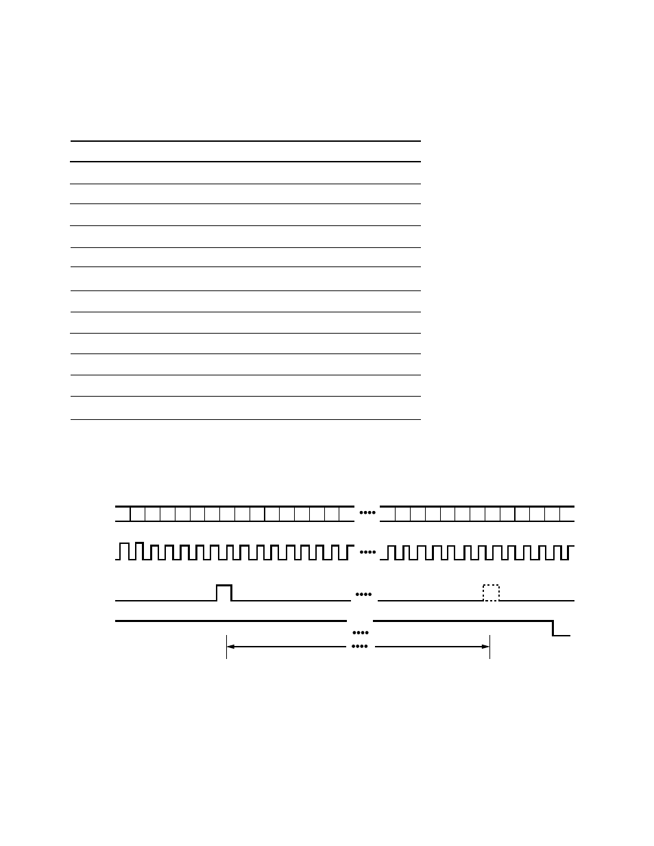
8.14 In Frame Declaration
RX_DATA[7:0]
RX_SONETCLK
RX_FRAME_IN
OOF
125
µ
s BETWEEN FRAMING PATTERN OCCURRENCES
A1
A1
A1
A2
A2
A2
C1
C1
C1
A1
A1
A1
A2
A2
A2
C1
C1
C1
The In Frame Declaration Timing Diagram (Figure 39) illustrates the declaration of in frame when
processing a 19.44 Mb/s stream on RX_DATA[7:0]. An upstream serial to parallel converter or byte
interleaved demultiplexer indicates the frame location using the RX_FRAME_IN input. The byte position
marked by RX_FRAME_IN may be controlled using the defined register bit. In frame is declared if the fram-
ing pattern is observed in the correct byte positions in the following frame, and in the intervening period
(125
µ
s) no additional pulses were present on RX_FRAME_IN.
Figure 39. In Frame Declaration