NORD Drivesystems BU0290 User Manual
Page 24
PROFINET bus module for NORD frequency inverters SK 200E
24
Subject to technical amendments
BU 0290 GB-4312
Alternatively, diagnosis can be performed via a Windows PC with the aid of NORD CON software (available
free of charge from . The necessary connection cable (RJ12 - SUB D9) is available from
Getriebebau Nord GmbH as part number 278910240. If necessary, an interface converter from SUB D9 to
USB2.0 is commercially available.
Terminal/
Designation
Function
Data
Description / wiring suggestion
Parameter
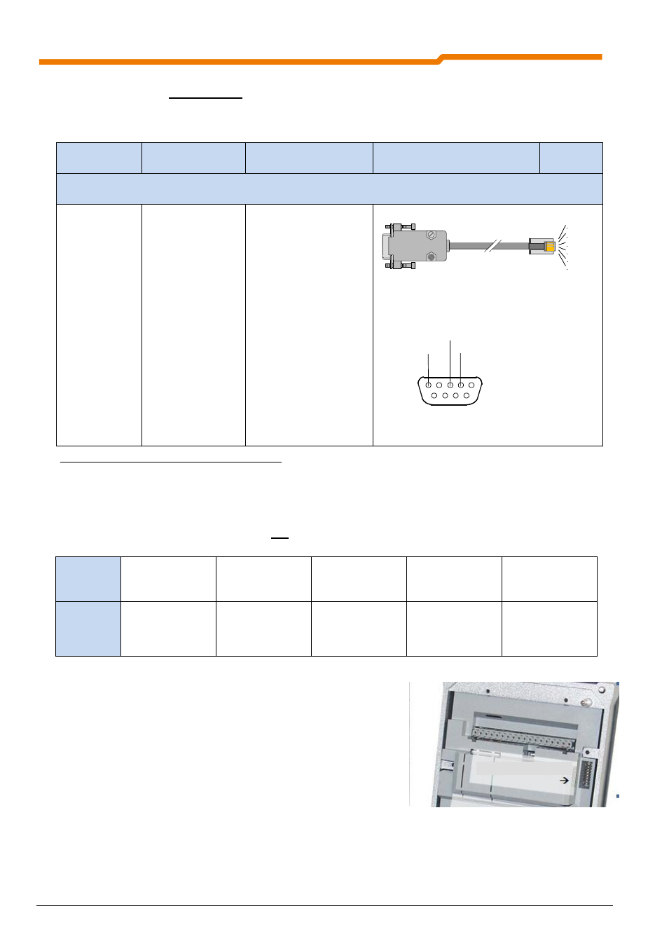
Accessory cable (optional) for PC connection
Adapter cable
RJ12 to SUB-D9
... for direct
connection to a PC
with NORD CON
software
Length 3m
Assignment RS 232
(RxD, TxD, GND)
Part. No. 278910240
TxD
RxT
GND
+24V
n.c.
n.c.
Assignment of SUB-D9 connector:
Pin2: RS232_TxD
Pin3: RS232_RxD
Pin5: GND
Table 10 Connection of RJ12 adapter cable to SUB-D9
No special settings are required to set up communication with the individual diagnostic tools.
The allocation of addresses is defined via the system bus addressing. The display of the diagnostic tool is
according to the following table, whereby the frequency inverter which is directly connected to the diagnostic
tool is automatically assigned the address
“0”.
Device
External
technology unit
Frequency inverter
with address 32
(system bus)
Frequency inverter
with address 34
(system bus)
Frequency inverter
with address 36
(system bus)
Frequency inverter
with address 38
(system bus)
USS
address
30
1
2
3
4
Note
Setting of the system bus address is carried out via two DIP
switches (DIP 1 and 2) on the underside of the SK 200E- frequency
inverter. For further details, please refer to the frequency inverter
manual (BU 0220). The address of the BUS module is defined as
“30”.
Fig. 3: DIP switches (system bus), frequency inverter
RxD
GND
TxD
6
1
5
9
Underside of SK 200E
8x DIP switches