2 electrical connection, 1 cable gland – NORD Drivesystems BU0290 User Manual
Page 14
PROFINET bus module for NORD frequency inverters SK 200E
14
Subject to technical amendments
BU 0290 GB-4312
2.2 Electrical connection
WARNING
THE DEVICES MUST BE EARTHED.
Safe operation of the devices requires that is installed and commissioned by qualified personnel
in compliance with the instructions provided in this Manual.
In particular, the general and regional installation and safety regulations for work on high voltage
systems (e.g. VDE) must be complied with as must the regulations concerning correct use of tools
and the use of personal protection equipment.
Dangerous voltages can be present at the motor connection terminals of the frequency inverter
even when the inverter is switched off. Always use insulated screwdrivers on these terminal fields.
Ensure that the input voltage source is not live before setting up or changing connections to the
unit.
Make sure that the inverter and motor are specified for the correct supply voltage.
2.2.1
Cable gland
Both the SK 200E connection unit and the bus module provide extensive facilities for the connection of all the
required cables. The cables may enter the housing via cable glands and be connected to the terminal bar.
However, appropriate round plug connections (e.g.: M12 round plug connectors in M16 cable glands) may be
fitted in order to provide a plug-in solution.
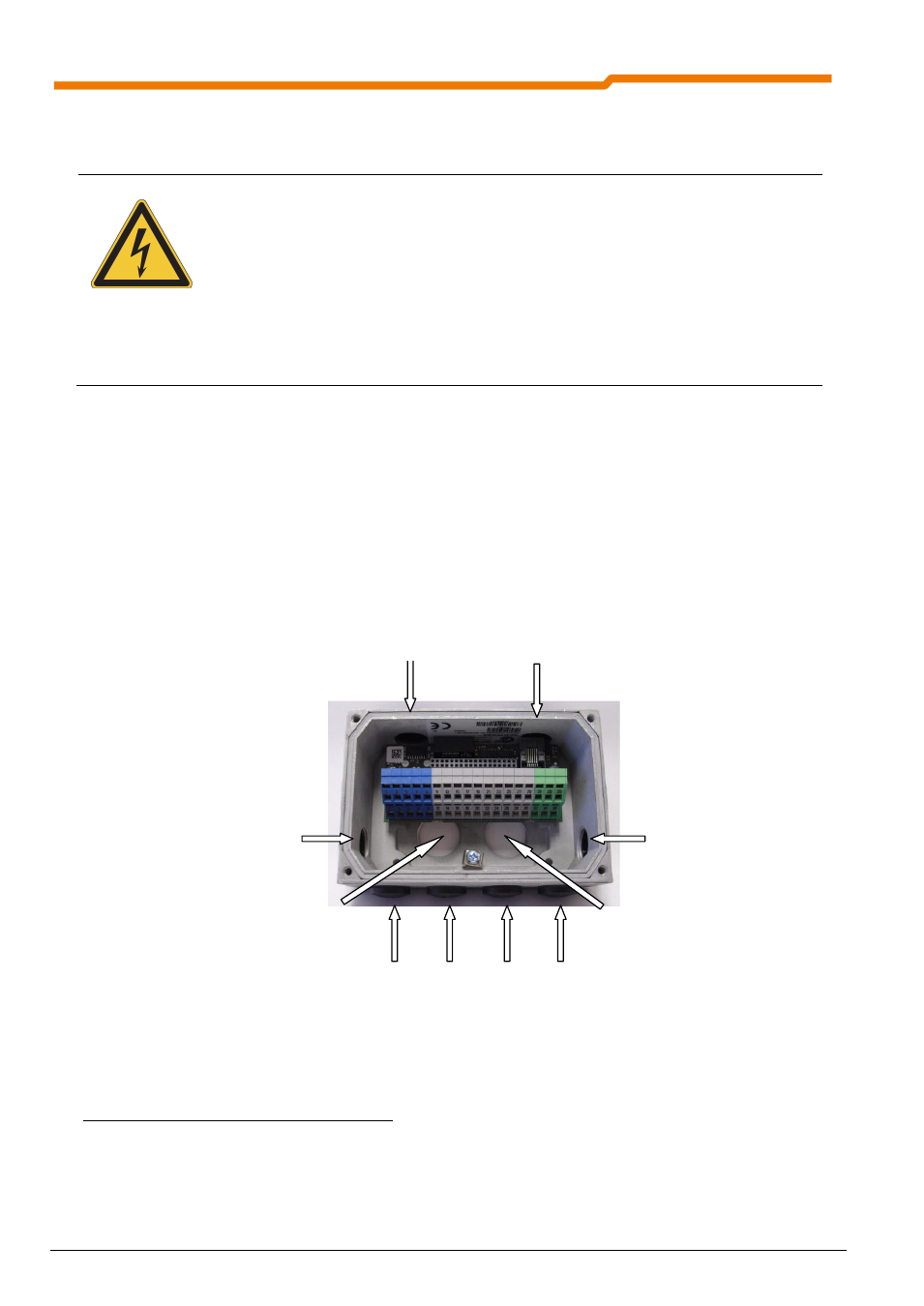
Fig. 2 Cable gland on the BUS module / connection unit
Outgoing cable, fixed
connection e.g. for system
bus or 24V supply
Incoming cable, fixed
connection e.g. for system
bus or 24V supply
Cable gland for system bus cable pair
and 24V supply for direct attachment
to SK 200E
No function,
do not use
Diagnostic
access
RJ 12 socket
Cable gland for system bus cable pair
and 24V supply for direct attachment
to SK 200E
M16 cable gland or installation of M12 round plug connection for:
24V and 24V (for DO) supply
System bus
I/O peripherals: sensors and actuators