2 control connections – NORD Drivesystems BU0290 User Manual
Page 15
2 Assembly and installation
BU 0290 GB-4312
Subject to technical amendments
15
2.2.2
Control connections
2.2.2.1 Field bus (PROFINET IO)
Specification
PROFINET IO
Max. baud rate 100 MBaud
Electrical isolation 500V
eff
Bus connection
2
RJ45
Bus termination
Performed automatically by the SK TU4-
… technology unit
Cable
Ethernet CAT-5 or better
Max. cable length
100m between two Ethernet bus modules
Supply voltage
24V
20%, current consumption
≈ 100mA
Reverse polarity protected
Status display
4 LEDs
Device address
via the PROFINET IO controller or parameterisation
PE
Connection via plug pins under the 24V supply
Shield
The shields of the two RJ sockets are connected together and connected to PE with a
high resistance and capacitance.
Table 2 Electrical specifications of the SK TU4-PNT
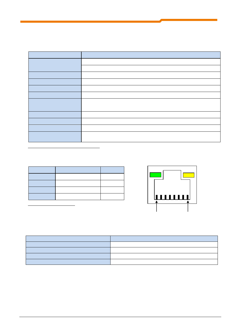
The field bus cable must only be connected to the two RJ45 sockets mounted on the front.
Signal
Name
RJ45 Pin
TX+
Transmission Data +
1
TX-
Transmission Data -
2
RX+
Receive Data +
3
RX-
Receive Data -
6
Table 3 RJ45 socket connections
2.2.2.2 Peripherals (system bus and IOs)
The PROFINET IO modules must be provided with a 24V DC (±20%, 100mA) control voltage. Wire end
sleeves must be used for flexible cables.
Designation
Data
Rigid cable cross-section
0.14 … 2.5mm²
Flexible cable cross-section
0.14 … 1.5mm²
AWG standard
AWG 26-14
Tightening torque (for screw terminals)
0.5 … 0.6Nm
Within the terminal box (unshielded cable section) the data cables (system bus) must be installed as short as
possible and of equal length. Associated data cables (e.g.: Sys+ and Sys-) must be twisted.
Pin 1
Pin 8