NORD Drivesystems BU0260 User Manual
Page 87
7 CANopen Data transfer
BU 0260 GB
Subject to technical amendments
87
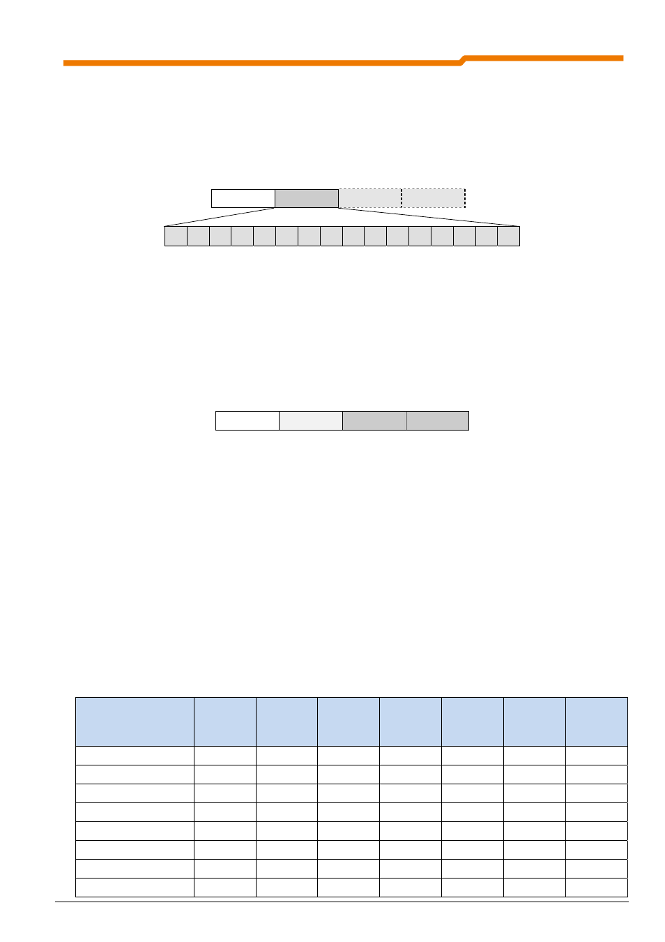
7.2.1.5 Actual value 1 (IW1)
The function of the first setpoint is set in the parameter "Function bus -actual value 1" (SK 200E: (P543[01]) or
SK 500E: (P543)) set (see relevant frequency inverter manual).
In the order telegram, actual value 1 follows immediately after the control word. Setpoint 1 is pre-set to the
transfer of the current output frequency of the frequency inverter (16 bit value).
PZD1 PZD2 PZD3 PZD4
ZSW IW1
IW2
IW3
15 14 13 12 11 10
9
8
7
6
5
4
3
2
1
0
The actual value is transferred as an integer in the range -32768 to 32767 (8000 hex to 7FFF hex), whereby in
the settings "actual frequency", "actual speed", "current" and "torque current", the values 16384 (4000 hex)
exactly correspond to 100% and -16383 (C000 hex) correspond to exactly -100%. Due to this resolution,
setpoints (depending on function) of up to ± 200% can be transferred.
7.2.1.6 Actual values 2 and 3 (IW2/3)
In addition to actual value 1, two further actual values can be transferred in the words "PZD3" and "PZD4".
PZD1 PZD2 PZD3 PZD4
ZSW
IW1
IW2
IW3
The definition of these two actual values corresponds to that of actual value 1.
If the transfer of a 32 bit actual value is necessary (Example: actual position), this must be divided into two 16
bit values, i.e. into two PZDs (position High and Low words).
The definition in the frequency inverter can then, for example, be made via the parameters:
PZD3:
„Bus function - actual value 2" (SK 200E: (P543[02]) or SK 500E (P544)) and
PZD4:
„Bus function - actual value 3" (SK 200E: (P543[03]) or SK 500E (P545))
7.2.2
The status machine
The frequency inverter passes through a status machine. The changes between various states are triggered
by the respective control commands in the process data control word. The actual status is returned in the
process data status word.
After switching on, the frequency inverter is in “Switch-on disabled” status. This status can only be ended by
transmitting the “Shut down (Off 1)” command.
The following bits indicate the status of the frequency inverter:
Status
Bit 6
Switch-on
disable
Bit 5
Emergency
stop
Bit 4
Disable
voltage
Bit 3
Fault
Bit 2
Operation
enabled
Bit 1
Standby
Bit 0
Ready for
switch-on
Not ready for switch-on
0
X
X
0
0
0
0
Switch-on
disabled 1 X X 0 0 0 0
Redy
for
switch-on 0 1 1 0 0 0 1
Activated
0 1 1 0 0 1 1
Operation
enabled 0 1 1 0 1 1 1
Fault
0 X X 1 0 0 0
Error
active
0 X X 1 1 1 1
Emergency
stop
active
0 0 1 0 1 1 1