NORD Drivesystems BU0260 User Manual
Page 18
Supplementary Manual CANopen for NORDAC SK 20E
18
Subject to technical amendments
BU 0260 GB
2.1.3
Installing the SK TU4-CAO Technology Unit
WARNING
Installation must be carried out by qualified personnel only, paying particular attention to
safety and warning instructions.
Modules must not be installed or removed unless the device is free of voltage. The slots
may only be used for the intended modules.
Mounting of the external technology unit remote from the frequency inverter is possible
with the additional wall-mounting kit (SK TIE4-WMK-TU).
Together with the BUS connection unit SK TI4-TU-BUS(-C) the technology unit SK TU4-CAO-…(-C) forms a
stand-alone functional unit. This can be attached to the SK 200E frequency inverter or installed separately by
means of the optional SK TIE4-WMK-TU wall-mounting kit.
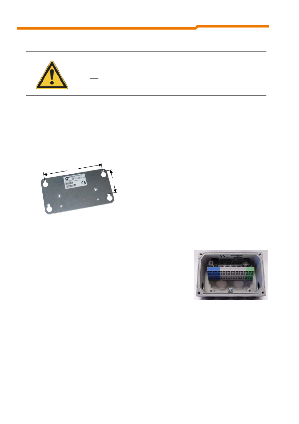
2.1.3.1 Dimensions of the SK TI4-WMK-TU wall-mounting kit
The optional wall-mounting kit has the following dimensions.
2.1.3.2 BUS connection unit SK T14-TU-BUS(-C)
Various cable glands closed by caps are located on the sides of the BUS
connection unit.
The following holes are available as cable inlets:
2 x 1 M20 x 1.5 (on sides)
4
M20 x 1.5 (underside)
2
M25 x 1.5 (rear side, without caps)
The transparent screw-on cover (M20 x 1.5) on the upper right serves as access to the diagnostic interface
(RJ12 socket, interface RS232/RS485). The upper left screw-on cover is not used.
136
58
Wall-mounting kit SK TI4-WMK-TU
External BUS connection unit = SK TI4-TU-BUS