NORD Drivesystems BU0260 User Manual
Page 27
2 Assembly and installation
BU 0260 GB
Subject to technical amendments
27
2.2.3
Configuration
The configuration for all CANopen module versions is identical. All necessary settings are made using the
hardware via a DIP- switch element (3+8- part switching block).
Addressing
Note:
CANopen address:
setting only via DIP switch in binary code
Address range:
1 … 63
Address changes:
only become effective after switching the BUS module off and on again
NOTE
If an application-specific configuration has been saved (memory object 1010
hex
), the
initialisation is not active after default mapping. In order to apply the new module ID
settings, the configuration must be reset to the factory settings (Parameter (P152) or
(Object 1011
hex
)) (See Section 4.7 “Saving the parameters”).
Termination resistor
The termination of the BUS system at both of its physical ends is carried out by connecting the relevant
termination resistors (DIP switch).
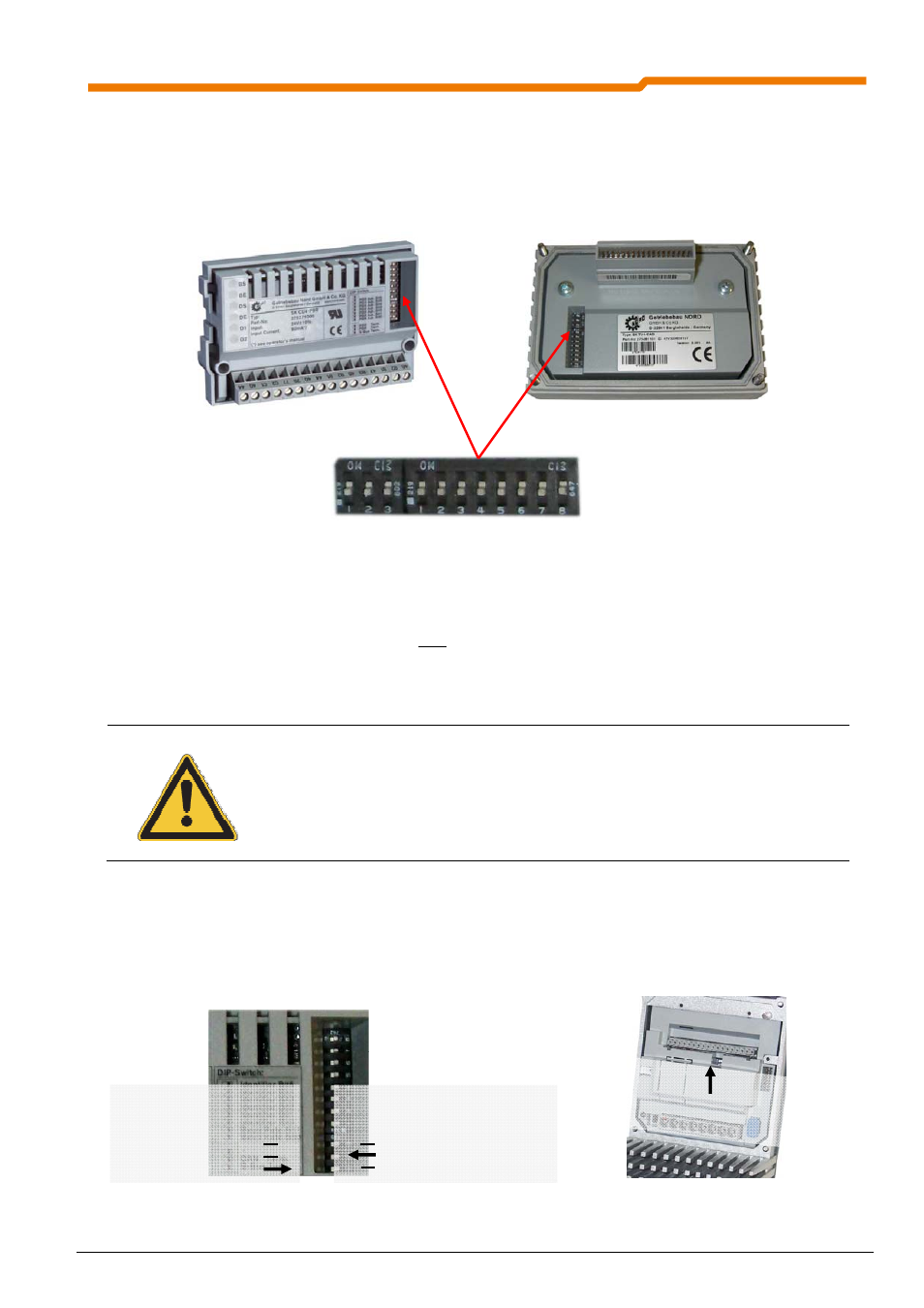
e.g.: SK CU4‐CAO
e.g.: SK 200E
CANopen module (view of DIP switch)
SK 200E (internal view)
System bus
termination resistor
Field bus (CANopen)
termination resistor
System bus
termination resistor
Customer unit SK CU4-CAO
Technology unit SK TU4-CAO
DIP switch 3 + 8 part
BUS termination
Addressing
Similar to
illustration